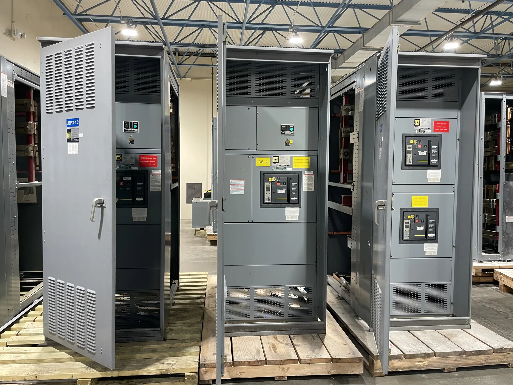
What switchgear assembly covers
Switchgear assembly turns an approved electrical and mechanical design into a coordinated equipment lineup. Depending on the specified product, work may include preparing enclosure sections, mounting devices, fitting barriers and supports, installing buswork, and completing connections called for by the drawings. The exact scope varies by design; the assembly stage should follow the released project documents rather than assumptions based on a typical lineup.
Assembly is distinct from design engineering, component procurement, field installation, and commissioning, even though it depends on coordination with each. Some components or services may come from outside suppliers or contractors. Buyers should ask which activities are performed by the manufacturer, which are supplied externally, and who reviews interfaces and records. This makes responsibility clear without assuming a particular shop arrangement or production capability.
Start with controlled design inputs
Before assembly, the project team needs a defined configuration. Useful inputs include the one-line diagram, equipment schedule, approved general arrangement, elevations, wiring diagrams, device and accessory schedules, and applicable project specifications. The documents should identify the equipment class, intended connections, compartment arrangement, incoming and outgoing cable requirements, and any specified options. Conflicts or missing details should be resolved through the project’s review process before they become shop-floor interpretation.
Revision control matters because a late change to a device, cable entry, metering arrangement, or compartment boundary can affect several drawings and parts. The buyer and responsible engineer should identify the governing revision and document how changes are approved. Submittals should clarify required reviews, permitted substitutions, and the information needed for release. A clear record helps the manufacturer coordinate the build with the design intent and gives reviewers a basis for checking what was assembled.
Plan the assembly sequence and interfaces
A workable sequence depends on the equipment layout and access to fastening points, wiring paths, and bus connections. Enclosure sections and internal supports generally need to be coordinated before devices and conductors obstruct access. The drawings should show mounting locations and clearances, while the assembly plan should account for components supplied separately and the order in which they are fitted. These details are design-specific and should be confirmed rather than presumed.
Interfaces deserve particular attention. Cable landing space, conduit or entry provisions, control wiring routes, barriers, doors, and removable panels can affect one another. A change in one area may create interference or limit access in another. Project teams should review these interfaces with the relevant drawings and identify who resolves discrepancies. If field conditions, building openings, or contractor-provided connections influence the layout, communicate those constraints early and document the agreed arrangement.
Coordinate bus design with assembly
Buswork is not simply a matter of choosing a metal bar that fits. The project design may address conductor material, cross-section, orientation, support spacing, joint details, insulation or barriers, and clearances. Electrical loading, enclosure arrangement, connections, and specified performance requirements influence the design. The responsible engineer must confirm the applicable requirements for the actual assembly; no single bus dimension or joint detail suits every switchgear configuration.
Assembly depends on that design being unambiguous. Drawings and bills of material should identify bus sections, supports, connection points, and required hardware. Joint preparation and fastening methods should follow the approved instructions and project requirements. Bracing, temperature-rise considerations, and possible movement or expansion should be evaluated as part of the design where applicable, not added as generic assumptions during assembly. Clarify how bus design changes are reviewed and reflected in controlled documents.
Use checks that match the specified equipment
Quality checks should be tied to the released drawings and the specific project requirements. Depending on scope, records may document component identification, mounting and orientation, bus installation, connection completion, barriers, wiring terminations, and visible workmanship. The project specification should define any required inspections, tests, acceptance criteria, and documentation. Do not assume that a particular test, certification, or listing applies to every design; confirm applicability for the specified equipment and assembly.
Assembly records also support a clean handoff. Ask what inspection documents, wiring records, marked-up drawings, or other closeout information will be provided, and when the responsible reviewers need them. If testing is required, clarify its scope, sequence, and acceptance criteria before production. Installation, testing, and maintenance belong to qualified personnel following applicable safety procedures. Any unresolved discrepancy should be documented and addressed through the designated approval process.
Resolve trade-offs and responsibilities early
Design choices can affect footprint, access, cable routing, component placement, and manufacturing coordination. A more compact arrangement may constrain working space or wiring paths; a layout with additional separation may affect enclosure dimensions. These are project trade-offs, not universal rules. The responsible engineer should weigh electrical requirements, site constraints, maintainability, and the owner’s preferences, then record the selected arrangement in the approved drawings.
When a supplier or contractor contributes components or work, identify the interface: what is furnished, what is assembled, what documents accompany it, and who verifies compatibility. Also establish the process for substitutions, nonconformances, and drawing changes. These questions reduce ambiguity across engineering, purchasing, manufacturing, and field installation. They are especially useful when the assembly relies on project-specific devices or connections that are not fully defined by a standard equipment description.
Prepare a useful assembly review package
Before requesting or approving a build, gather the one-line diagram, equipment schedule, layout drawings, wiring requirements, bus specifications, project standards, and known site constraints. Mark required options and identify items still awaiting confirmation. State the intended review milestones and required records, and name the parties responsible for design decisions and approvals. This checklist helps the manufacturer identify open questions without treating incomplete information as a final production release.
For a quotation or technical review, describe the application, equipment class, configuration, required components, and project schedule needs, while allowing the actual delivery date and design details to be confirmed against the specification. South Carolina Switchgear Builders manufactures new switchgear and switchboards to specification, with US-built equipment, all-American components, short lead times as a general positioning, and nationwide shipping. Once the design inputs and responsibilities are clear, the assembly plan can be coordinated against the approved project documents.