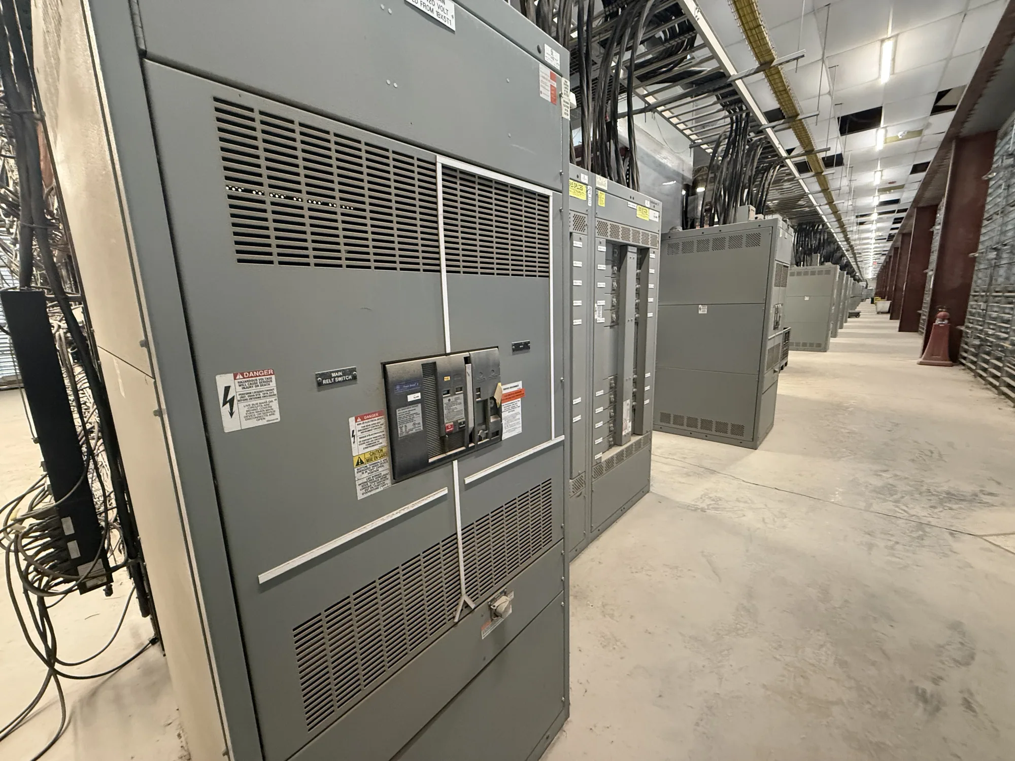
Define the busbar design scope
Busbars are conductive paths that connect and distribute power within switchgear and switchboards. Their design is not a standalone choice of metal or dimensions: it must fit the assembly’s electrical duty, physical arrangement, connections, enclosure, and intended operating environment. This guide focuses on the information needed to evaluate bus construction for new equipment, rather than treating a busbar as a generic component.
Key specification topics include material, cross-section, support and bracing, temperature rise, joints, and provisions for thermal expansion. These details interact. Changing the bus layout can affect connection locations and clearances; changing a joint or support arrangement can affect the mechanical design. The responsible project engineer and equipment manufacturer should confirm the proposed construction against the complete assembly specification.
Start with operating and fault-duty inputs
Provide the required system voltage, continuous current, phase arrangement, frequency where relevant, and the equipment’s intended function. Identify incoming and outgoing connections, load distribution, and any provisions such as a neutral bus. Do not assume that a nominal current value alone defines the bus requirement: the complete design must account for the specified operating conditions and the assembly configuration.
Fault-duty information is also essential. Share the available fault current or the project’s required short-circuit withstand information, along with the expected protective-device arrangement and relevant clearing assumptions if established by the project engineer. Bus supports and bracing must be evaluated for the mechanical forces associated with the specified fault conditions. The appropriate construction depends on verified design details; there is no single bus dimension or support spacing suitable for every assembly.
Compare material and cross-section in context
Bus material and cross-section influence conductivity, physical size, connection methods, and thermal behavior. Copper and aluminum are common options, but neither should be selected by a broad rule of thumb. Evaluate the offered material against the project requirements, equipment design, connection interfaces, environmental exposure, and any owner or engineering preferences. Confirm that mating surfaces, hardware, and transition points are compatible with the specified construction.
A larger cross-section does not by itself establish that a bus design meets a project’s current or temperature-rise requirements. Enclosure dimensions, ventilation, neighboring heat sources, surface condition, connection resistance, and the arrangement of conductors can all matter. Ask the manufacturer to identify the proposed bus material and configuration and to confirm how the complete assembly will be evaluated for the project conditions. Ratings and test documentation must be verified for the specific design.
Account for bracing, joints, and expansion
Bus supports and bracing hold conductors in position and help the assembly withstand mechanical stresses. Their layout must be considered alongside fault duty, conductor geometry, insulation or barriers, and the clearances required by the equipment design. Provide the project’s specified withstand criteria and ask how they apply to the proposed assembly. Avoid assuming that a support arrangement from another lineup transfers to a different design.
Joints deserve similar attention because they are interfaces within the current path and may also be service or assembly points. Specify connection locations, field-connection expectations, and any required access or inspection provisions. Bus conductors also change dimension as temperature changes. The design should account for thermal movement in a way compatible with supports, joints, enclosure geometry, and connected equipment. The manufacturer and responsible engineer should resolve these details for the actual arrangement.
Evaluate the enclosure and operating environment
Describe where the equipment will operate, including indoor or outdoor placement, ambient conditions, ventilation constraints, elevation or other project-specific environmental factors, and exposure to contaminants or moisture where applicable. Explain the enclosure and room limitations, cable entry direction, and space available for installation and future access. These inputs help determine whether the proposed bus layout and thermal assumptions fit the intended application.
For example, a project comparing low-voltage switchgear with electrical switchboards should not assume that similar bus terminology means identical construction, ratings, or evaluation. The engineer must verify the equipment type, voltage class, required current and fault duty, available space, and applicable assembly requirements for each option. If a switchboard is considered, ask whether UL 891 applies to the specific eligible design and verify the assembly listing; do not transfer that standard to medium-voltage switchgear.
Prepare a useful specification and review package
Before requesting a proposal for new equipment, assemble the one-line diagram, system voltage and current requirements, fault-duty data, source and load connection details, grounding arrangement, and enclosure constraints. Include the required bus material if specified, or ask for a clearly identified alternative. Note environmental conditions, cable or busway interfaces, access requirements, and any owner standards that the design must address.
Request drawings or design documentation that identify bus arrangement, material, connection points, supports, and applicable ratings. Ask which project assumptions remain open and what information is needed to close them. Confirm that proposed temperature-rise, short-circuit, listing, testing, and standards claims apply to the exact assembly being offered. Availability and lead time depend on the final configuration and must be confirmed for the order.
Coordinate decisions before equipment release
Use a review sequence that brings the project engineer, equipment manufacturer, installer, and other responsible parties together before design release. Resolve electrical duty, layout, interfaces, access, and environmental assumptions before fabrication. If site conditions or connected equipment change, determine whether the bus design and supporting documentation need revision rather than relying on an earlier selection.
A complete busbar specification is one that ties construction choices to documented project requirements and clearly identifies what still needs confirmation. With the inputs organized and trade-offs reviewed, the design team can compare equipment proposals on a consistent basis and advance a configuration suited to the intended distribution system.