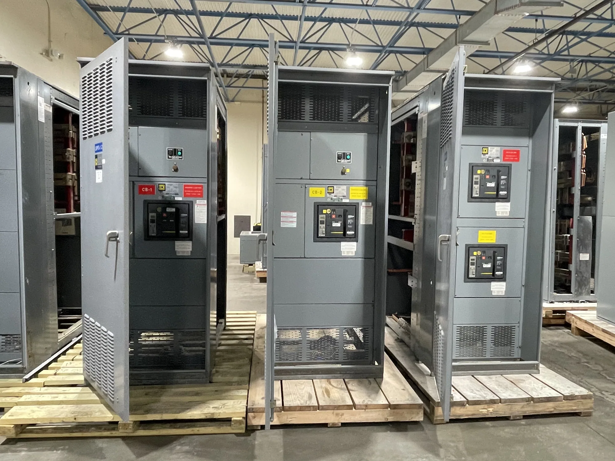
What 120/240 V identifies
A 120/240 V designation describes nominal system voltages, but it does not fully identify the electrical service or establish a complete equipment rating. In one familiar arrangement, 120 V is measured from either ungrounded conductor to neutral, while 240 V is measured between the two ungrounded conductors. That relationship is associated with a particular phase and conductor arrangement; it should not be assumed from the voltage label alone.
Also distinguish nominal system voltage from an assembly’s maximum voltage rating and insulation requirements. Those are related design inputs, not interchangeable terms. The responsible engineer should identify the actual source and intended application, then confirm that the proposed equipment documentation addresses the system conditions. A label that includes “120/240 V” is not enough to establish suitability for every system carrying those numbers.
Confirm phase and conductor arrangement
Many 120/240 V applications use single-phase, three-wire service, but the project’s actual source must establish whether that is the arrangement in question. Specify the number of phases and conductors, identify which conductors are grounded, and explain how neutral is used. If the source is a transformer or another distribution arrangement, provide its relevant configuration rather than relying on a shorthand description.
Other systems can present voltage pairs that look similar while differing in phase relationships, conductor functions, or how loads are supplied. Those differences affect the equipment’s bus arrangement, switching, overcurrent protection, and connection points. Do not infer a split-phase arrangement merely because both 120 V and 240 V appear in project notes. Resolve discrepancies among the one-line diagram, source documentation, and service information before final equipment selection.
Grounding, insulation, and fault duty
Provide the grounding method and clarify the intended neutral-to-ground relationship at the equipment. The design team should identify which conductors are switched or protected and how the equipment interfaces with the grounding and bonding system. These decisions depend on the actual installation and applicable design requirements; they should not be filled in from a generic voltage description.
Available fault current is another independent selection input. A nominal 120/240 V value does not state the prospective fault duty or establish that a particular assembly can withstand and interrupt the conditions at its installation point. The engineer should obtain source or utility fault data, identify upstream protective devices, and evaluate the equipment ratings and coordination requirements against the project design. Confirm insulation and other electrical ratings from the proposed assembly documentation.
Keep system voltage separate from product class
Specify the voltage at the point of connection and the equipment’s required ratings as separate, explicit items. A system voltage should not be treated as a complete equipment specification, and a generic maximum-voltage figure should not be substituted for the nominal service description. The responsible engineer and equipment supplier can review the one-line and source data to determine whether the intended configuration is appropriate.
Selection also depends on the equipment’s function and scope: for example, the incoming source, outgoing circuits, switching and protective devices, enclosure, and required interfaces. If a project calls for a switchboard rather than switchgear, name the intended equipment accurately. Any applicable product standard, listing, and assembly details must be confirmed for the specific design; do not assume that a voltage designation alone determines them.
Trade-offs and assumptions to resolve
The key design tradeoff is not simply choosing between 120 V and 240 V. It is matching equipment connections and protection to the real phase and conductor arrangement, expected loads, available source, and fault conditions. A configuration that suits one 120/240 V service may not suit another arrangement that shares the same nominal voltage notation. Clear documentation reduces the risk of ordering equipment around an incorrect assumption.
Before specifying a proposed configuration, ask whether the service is single-phase or another arrangement, how neutral is derived and used, which loads require each voltage, and what switching or protective functions are required. Confirm these answers with the project engineer and source documentation. Do not assume a particular manufacturer offering, available configuration, or standard assembly based only on the voltage pair; custom equipment requirements and feasibility need project-specific review.
Information to provide for a specification review
Prepare the latest one-line diagram, source or utility data, nominal voltage, phase and conductor count, grounding method, and available fault current. Include the equipment location, incoming and outgoing connection requirements, load information, protective-device intent, enclosure conditions, and any governing project specifications. If a value is unknown or pending, label it that way instead of estimating; the responsible engineer can identify what must be resolved before design release.
South Carolina Switchgear Builders manufactures new equipment to specification, with US-built equipment, all-American components, and nationwide shipping. Availability and actual lead times depend on the order and must be confirmed. Share the project documents and open questions for a technical review of the proposed scope. The project engineer must verify system suitability, ratings, standards, and interfaces against the final design and supplied equipment documentation before procurement and installation.