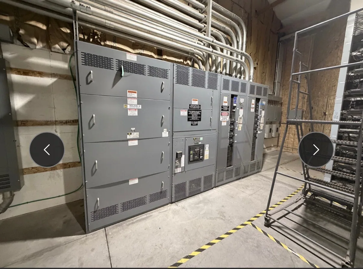
Define the control-wiring scope
Switchgear control wiring carries signals and control power among devices within an assembly and, where specified, to external systems. The scope may include breaker control circuits, protective relays, indication, alarms, metering, and communication interfaces. The approved project documents—not assumptions about a typical lineup—determine which components and connections belong in the new equipment.
Several documents make that scope reviewable: control schematics show circuit logic, terminal plans identify connection points, point lists define signals, and interface schedules assign connections between the switchgear and other equipment. Wire and terminal labeling then help relate physical connections to those documents. A consistent document set reduces ambiguity during fabrication, installation, and commissioning.
Translate operating sequences into circuits
Begin with the intended sequence of operation. For each breaker or controlled device, clarify what initiates an operation, what permissives or interlocks apply, what indications confirm status, and what conditions create alarms. The responsible project engineer should confirm the logic and protection requirements. A wiring drawing should express an approved design, not become a substitute for decisions about system behavior.
Inputs and outputs need explicit definitions. A point list can state the signal name, source, destination, expected contact or signal type, and whether it is an indication, command, alarm, or measurement. Confirm control-power sources, circuit protection, polarity or reference conventions where relevant, and any required isolation between circuits. These details influence wiring, terminals, device selection, and the information available to operators.
Coordinate metering and communications
Metering and instrumentation add another layer of interfaces. Identify which measurements are required, where they originate, and which equipment or monitoring system receives them. Confirm instrument transformer and meter arrangements against the project design, including signal wiring and terminal assignments. Measurement needs should be coordinated with protection and operating functions so that a point is not omitted, duplicated, or assigned to the wrong destination.
For communications, specify the intended devices, protocol, network connection, data points, and responsibility for configuration. Determine whether the equipment scope includes a communications device or only provisions and terminals for an external system. Network architecture, addressing, access control, and cybersecurity responsibilities should be assigned by the project team. A protocol name alone does not define the complete interface or establish that two systems are compatible.
Make responsibility boundaries visible
Control wiring may cross several organizations: the switchgear manufacturer, protection or metering suppliers, the installing electrical contractor, and the controls or network integrator. Mark the boundary at a practical connection point, such as a terminal block or specified connector, and identify which party supplies, wires, configures, and verifies each segment. Confirm who provides external cables and who resolves changes to points or logic.
Review interfaces before drawings are released for fabrication. Compare schematics, point lists, device schedules, and external connection requirements for consistent names and destinations. Capture owner and engineer comments in a controlled revision rather than relying on informal markups. If an external supplier's device information is pending, identify the open item and its effect on the design; do not silently assume dimensions, terminal numbers, or signal behavior.
Documents that reduce field ambiguity
Useful control-wiring documentation is specific enough to follow across the equipment boundary. Provide approved schematics, terminal plans, device schedules, point lists, and interface details appropriate to the project. Identify drawing revisions and equipment designations consistently. Where wiring diagrams use symbols or abbreviations, define them so reviewers and installers can interpret the same circuit intent.
Verification should follow the approved scope and applicable project procedures. Manufacturing checks may compare installed wiring and labels with released drawings, while project acceptance and commissioning requirements should be agreed by the responsible parties. Do not assume a particular test, record, or acceptance criterion is included unless the specification confirms it. Installation, testing, and maintenance are for qualified personnel following applicable safety procedures.
Prepare a useful control-wiring checklist
Before requesting or reviewing new switchgear, assemble the latest one-line diagram, control schematics or sequence narrative, protection requirements, metering needs, point list, communications requirements, and external interface drawings. Include preferred device designations, terminal conventions, and any owner review or submittal requirements. Identify documents that are preliminary, who will approve them, and when confirmed supplier information is expected.
Then ask practical questions: Which functions are included in the assembly? Where do manufacturer and contractor responsibilities divide? Who supplies and configures relays, meters, and network components? Which points must be exchanged, and how will revisions be tracked? South Carolina Switchgear Builders manufactures new switchgear and switchboards to specification, with US-built equipment, all-American components, short lead times, and nationwide shipping. Final configuration, availability, delivery timing, ratings, testing, and applicable listing must be confirmed for the specific design. Clear answers at the documentation stage give the project team a more dependable basis for fabrication and coordinated installation.