Define the scope before naming devices
Instrumentation and communications should be specified around operating decisions, not a list of fashionable features. Start by identifying what facility personnel need to measure, what conditions they must recognize, and which actions or records depend on that information. The switchgear specification can then distinguish local indication, remote monitoring, protective functions, and control interfaces instead of treating them as one undifferentiated communications package.
Decide which assemblies and sections are in scope, such as service-entrance switchgear, distribution sections, or generator paralleling switchgear. State whether the requirement covers metering, breaker or switch status, alarms, event records, communications hardware, and connections to a supervisory system. Clarify what belongs to the switchgear manufacturer and what is furnished or configured by the controls integrator, electrical contractor, or owner.
Build a point list around decisions
A usable point list names each required value or condition, its source, where it must be available, and how it will be used. For metering, specify the electrical quantities needed, the relevant circuit or bus, whether readings are local or remotely collected, and any project-defined accuracy or display requirements. The responsible engineer must confirm measurement needs and compatible devices for the actual design.
For status and alarms, avoid vague requests such as “all breaker points.” Identify the states that matter—for example, open or closed indication, trip indication, or a defined equipment alarm—and specify whether each is an indication, an alarm requiring action, or an event to record. Confirm how a point is generated, how loss of its signal is treated, and whether the required state is available from the selected device and wiring arrangement.
Use a consistent schedule with a point name, equipment identifier, source device, signal or data type, destination, and responsible party. Add units, scaling, update expectations, alarm priority, or event timing only where the application requires them. A point list is not complete merely because a device can expose many values: each point needs an owner and a clear operational purpose.
Choose protocols and interfaces deliberately
Specify the accepted protocol and interface at each boundary rather than writing only “network communication.” Identify the system that will receive data, the interface it accepts, and any project requirements for serial or Ethernet connections, addressing, device discovery, time synchronization, or data mapping. Confirm compatibility among meters, protective devices, gateways, and the receiving system before the equipment design is finalized.
Protocol support alone does not establish that integration will work as intended. Ask who supplies and configures gateways, who develops point maps, who assigns addresses, and who validates end-to-end data. Define whether communications are read-only or include commands, and keep remote control requirements separate from monitoring points. Network topology, switch ports, cabling, and configuration may be outside the switchgear package, so state scope boundaries plainly.
Set cybersecurity and control boundaries
Cybersecurity expectations should be coordinated with the facility’s IT and operational-technology requirements. Specify who approves network connections, credentials, remote access, firmware or configuration changes, and the handling of security documentation. Ask whether the project requires network segmentation, access controls, logging, or restrictions on external connectivity. These are project decisions; do not assume that a communications device automatically satisfies an owner’s security policy.
Make the distinction between monitoring and control explicit. If commands are contemplated, identify the authorized operating system, permitted commands, interlocks, and approval responsibilities for the responsible engineer to review. Define fallback expectations for loss of communications without implying that communications replace protective functions or local operating procedures. Equipment configuration and safety provisions must be confirmed for the specific design.
Review system-level tradeoffs
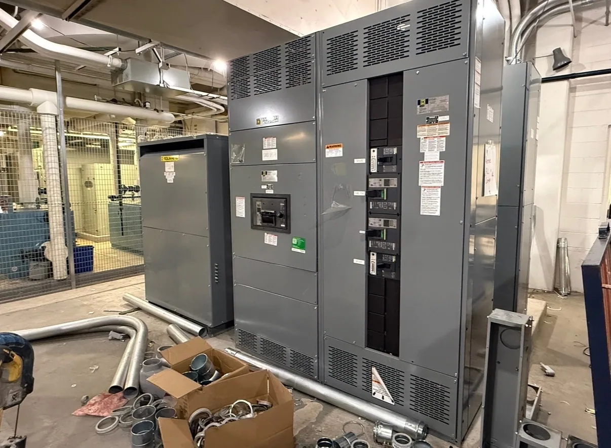
Consider a facility coordinating Service-Entrance Switchgear with Generator Paralleling Switchgear. The engineer may want utility-side measurements, source and breaker status, generator operating information, and selected alarms at a common supervisory system. That concept does not establish which devices provide each point, whether values are shared between assemblies, or which system performs sequencing; those details require project-specific engineering.
Before accepting the interface, verify signal ownership, point naming, data direction, command authority, and behavior when a device or network path is unavailable. Confirm whether the receiving system needs raw measurements, calculated values, or event records, and how timestamps are handled. More data can increase integration effort without improving decisions, while a narrow point list can omit information needed for troubleshooting. Resolve that balance with operations and controls stakeholders.
Prepare a complete specification package
For an RFQ, provide single-line diagrams, equipment scope and identifiers, the point list, accepted protocols and interfaces, network boundary assumptions, and named integration responsibilities. Include the receiving-system information available to the project team and identify unresolved choices as questions rather than implied requirements. Request proposed device and interface details for review against the specification; availability and final configuration depend on the actual order.
Also state documentation and acceptance expectations: device schedules, connection or interface drawings, point maps, configuration records, and any project-defined communications checks. Ask the responsible engineer to identify applicable codes, owner standards, and required approvals for the specific installation. Coordinate environmental site conditions and equipment requirements separately, since they can affect device selection and assembly details.
Coordinate review before release
Before approving the design, compare the point list with the one-line and controls narrative, then confirm each required point has a source, destination, interface, and accountable party. Close open questions about cybersecurity, command authority, network infrastructure, and integration testing. This review gives the equipment supplier and project integrator a defined basis for coordination and helps prevent late changes caused by assumptions about who provides or configures a connection.
Instrumentation is most useful when it supports specific operating and maintenance decisions and arrives at the intended system in an agreed format. Keep the specification focused on required information, verified interfaces, and clear scope boundaries. Have qualified project personnel confirm the final design, configuration, and acceptance procedures before equipment release and installation.