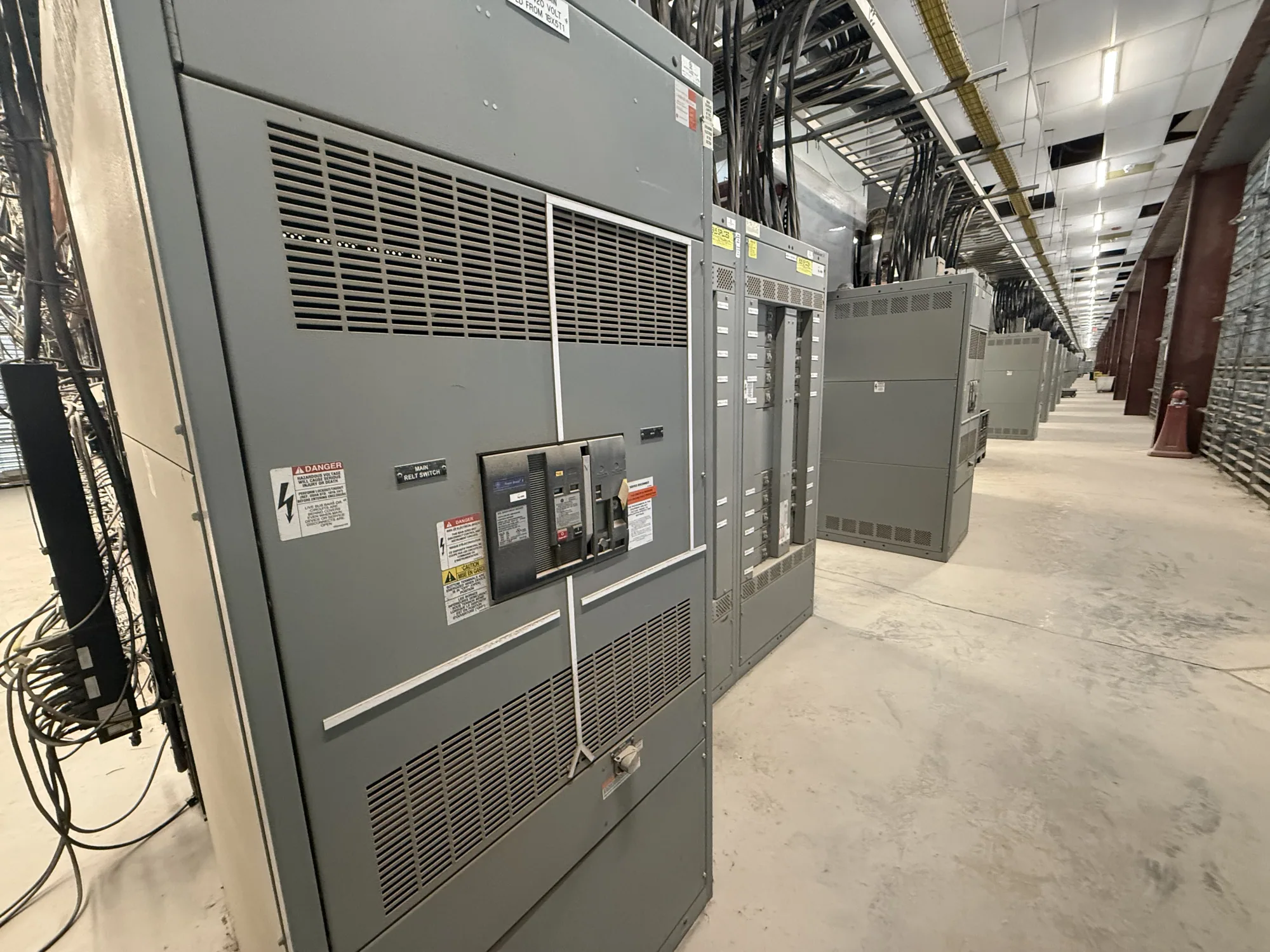
Define the service-entrance equipment scope — Service-Entrance Switchgear for South Carolina
Service-entrance switchgear is main distribution equipment specified at the point where an electrical service enters a facility. Its function and arrangement depend on the project design, the serving utility’s interface, and the equipment specified by the responsible engineer. For buyers, the first task is to establish exactly what the assembly must include and where its responsibilities begin and end.
It is important to distinguish service-entrance switchgear from related equipment. A switchboard may be appropriate for some low-voltage distribution designs, while medium-voltage switchgear is a different equipment class. A service disconnect, protective devices, metering provisions, and downstream distribution sections may be included or supplied separately. Confirm the required scope on the one-line diagram and equipment specifications rather than assuming a standard package.
Resolve the utility interface early
The service connection affects the equipment arrangement, but utility rules and approval processes vary. Identify the service configuration, point of connection, available fault-current information, metering requirements, and any utility-furnished or utility-controlled components. Ask the serving utility and project engineer to confirm applicable requirements before finalizing the equipment design. Do not assume that a general equipment description establishes acceptance by a particular utility.
Clarify who is responsible for each interface: the utility, owner, engineer, electrical contractor, and equipment manufacturer may have different roles. Document cable entry direction, termination space, access requirements, metering boundaries, and any required barriers or compartments. Resolving these details during quotation and design review can reduce conflicts with service conductors, building openings, and adjacent electrical equipment later in the project.
Match voltage and current ratings to the system
Specify the system’s nominal voltage and configuration, then have the responsible engineer verify the equipment’s applicable voltage rating and insulation requirements. A 480 V-class system is low voltage; 5 kV- and 15 kV-class systems are medium voltage. Those classes are not interchangeable, and the correct selection depends on the actual system and design. Confirm the stated rating against project documents rather than inferring it from a facility description.
Normal load current is only one input to current-rating decisions. The engineer should establish bus and device ratings, expected loading, ambient and operating temperatures, enclosure conditions, and any applicable derating factors. Fault-current withstand and protective-device requirements also need project-specific review. Provide the available study data and required coordination information; do not treat a nominal voltage or a single current figure as a complete equipment specification.
Specify disconnecting, grounding, and bonding details
Define the required service disconnect arrangement and identify the devices, operating method, and provisions expected in the assembly. Grounding and bonding must follow the project design and applicable requirements, including the intended relationship between grounded conductors, equipment grounding paths, and service conductors. The equipment configuration should reflect the engineer’s documented design, not an assumption made during purchasing.
Ask the project engineer to confirm the system grounding method and the locations where bonding is required. Include relevant drawings and notes in the request for quotation, and flag any unresolved utility or authority review. Installation, testing, and maintenance are tasks for qualified personnel following applicable safety procedures. Procurement documents should define the equipment and interfaces, not direct unsafe work practices.
Weigh operating needs against future flexibility
Consider a facility with production lines, motor loads, and planned expansion. The present load schedule may not capture how future equipment changes demand, so the owner and engineer should discuss expected additions and operating priorities. A larger or more flexible arrangement can affect footprint, cost, protection coordination, and the amount of equipment that must be specified now. Compare alternatives against documented plans rather than an unspecified allowance.
Review access for operation and maintenance, cable routing, room clearances, and coordination with downstream distribution. If backup generation or parallel operation is part of the project, define that requirement separately and coordinate it with the service-entrance design; generator-paralleling equipment is not automatically part of the service entrance assembly. Confirm how normal and alternate sources interact in the project documents before selecting equipment.
Prepare a useful equipment request
A complete inquiry should include the one-line diagram, nominal system voltage and configuration, load information, required service and device ratings, available fault-current data, grounding method, and known utility criteria. Add the intended installation environment, cable entry and termination needs, space constraints, metering requirements, and applicable project specifications. Identify what remains subject to engineering or utility confirmation so assumptions are visible.
- State whether the requested equipment is low-voltage or medium-voltage and provide the specified ratings.
- Mark included and excluded components, interfaces, and responsibilities on the project documents.
- Provide required drawings, review milestones, submittal expectations, and delivery destination.
South Carolina Switchgear Builders manufactures new switchgear and switchboards in the United States, with all-American components, custom configurations to specification, short lead times, and nationwide shipping. Availability, delivery timing, ratings, testing, listing, and standards applicability require confirmation for the specific design. For eligible low-voltage switchboards, UL 891 applicability and assembly listing must be verified; it does not establish a requirement or listing for medium-voltage switchgear.
Before release, have the engineer, owner, contractor, and manufacturer review the same approved scope, ratings, and interface details. Confirm utility and authority approvals through the responsible parties, and resolve drawing comments before manufacturing begins. This coordinated approach helps buyers specify service-entrance equipment that fits the documented electrical system and project constraints without relying on generic assumptions.