Where medium-voltage distribution fits — Medium-Voltage Switchgear for Water and Wastewater Facilities
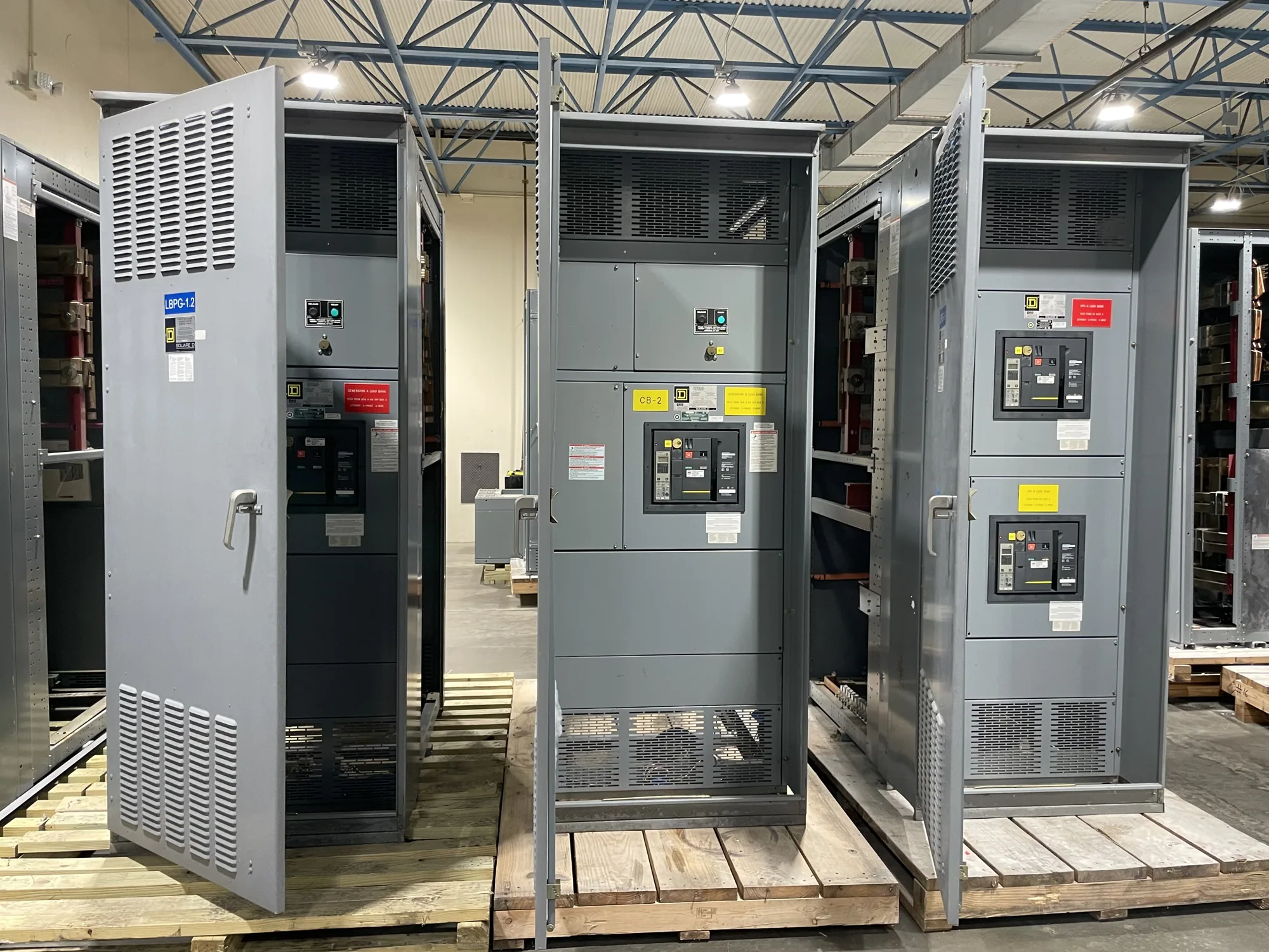
Water and wastewater facilities may include intake, treatment, pumping, and process areas with electrical loads spread across buildings or sites. In a project scenario, medium-voltage switchgear can receive or distribute power to transformers, motor-feeding equipment, or other sections of a facility’s electrical system. Its role depends on the one-line diagram and the boundary between utility, facility, and downstream distribution; it should not be selected from the application name alone.
For a new equipment purchase, first identify the switchgear’s place in the system. Is it a service entrance, a main distribution lineup, or a feeder section supplying a defined load? Is it indoors, in a separate electrical building, or exposed to outdoor conditions? These answers shape the required configuration and interfaces. The facility’s engineer should establish the electrical design basis and determine which equipment belongs in the manufacturer’s supply scope.
Match voltage and system configuration
Specify the nominal system voltage and the equipment maximum voltage required by the project, rather than using “medium voltage” as a complete rating. Confirm system frequency, grounding method, phase arrangement, bus configuration, and the source and feeder arrangement with the responsible engineer. The project specification should also address insulation requirements and any applicable design conditions. These details must be evaluated together; a voltage label alone does not establish compatibility.
Ask how the lineup interfaces with upstream protection, downstream transformers or loads, and any parallel sources or transfer arrangement. Confirm the required short-circuit and continuous-current ratings from the system study and project documents. Do not infer these values from motor horsepower or from another facility. If the one-line diagram is preliminary, identify open design decisions and establish who will resolve them before final equipment configuration.
Account for motor loads and starting
Pumping and process applications can include large motors whose starting method and operating profile affect the electrical design. Provide motor nameplate data, starting method, expected starting sequence, frequency of starts, and any known operating scenarios. The project engineer can assess voltage dip, protection coordination, and whether the specified switchgear and associated equipment suit those conditions. Do not assume that a standard feeder arrangement supports every motor-starting scheme.
Clarify what each feeder serves and how operators expect equipment to be isolated for planned work. The required switching devices, interlocks, metering, and protective-relay functions should follow the approved one-line diagram and control philosophy. For pumps that are intended to operate in sequence or as standby units, describe those modes and any control-system signals that need to cross the switchgear boundary. The exact interface is a project-specific design matter.
Specify protection and control interfaces
Protective-relay requirements should be stated as functions and interfaces, not left to assumptions about a facility type. Identify the protection scheme, relay or control equipment requirements, instrument-transformer data, trip and close circuits, alarms, and communications signals required by the project. Confirm which devices and wiring are included in the equipment scope and which are provided by the engineer, controls contractor, utility, or site team.
Remote monitoring may be important where electrical rooms are distant from process operations, but the switchgear specification should define what information is exchanged and through which approved interface. Supply the control narrative, signal list, communications requirements, and available control power information when applicable. Resolve ownership of settings, programming, coordination studies, and field commissioning separately; equipment supply does not by itself establish those engineering or field-service responsibilities.
Evaluate location and environmental exposure
Some facilities have outdoor equipment areas, washdown nearby, humid spaces, or exposure to corrosive agents; others do not. Describe the actual installation environment rather than assuming all water and wastewater sites share the same conditions. Provide location, enclosure requirements, ambient conditions, elevation if relevant to the project specification, and any known chemical, moisture, dust, or ventilation concerns for the responsible design team to evaluate.
Isolation and access planning also depend on the room layout and operating constraints. Share equipment-room dimensions, cable entry preferences, working clearances established by the project design, and any restrictions on moving or replacing sections. If a planned outage limits installation sequencing, state the constraint early. Qualified personnel must handle installation, testing, and maintenance under applicable safety procedures; purchasing discussions should not be treated as instructions for energized work.
Prepare a useful RFQ and coordinate scope
A clear request for quotation should include the latest one-line diagram, project specification, nominal and maximum voltage requirements, ratings established by the engineer, feeder schedule, motor data, protection and control requirements, and installation environment. Add preferred lineup arrangement, cable entry, accessories, documentation needs, delivery destination, and the requested project schedule. Mark deviations, alternates, and unresolved details so they can be reviewed rather than silently assumed.
South Carolina Switchgear Builders manufactures new switchgear and can configure equipment to specification, with US-built equipment, all-American components, and nationwide shipping. Availability and lead time depend on the order and must be confirmed. During quotation and submittal review, coordinate design questions, scope boundaries, approved drawings, and delivery requirements with the project team. Verify ratings, listing applicability, testing, and standards against the actual proposed assembly before release. This process gives the facility and manufacturer a defined basis for supplying equipment that fits the project rather than relying on broad application labels.