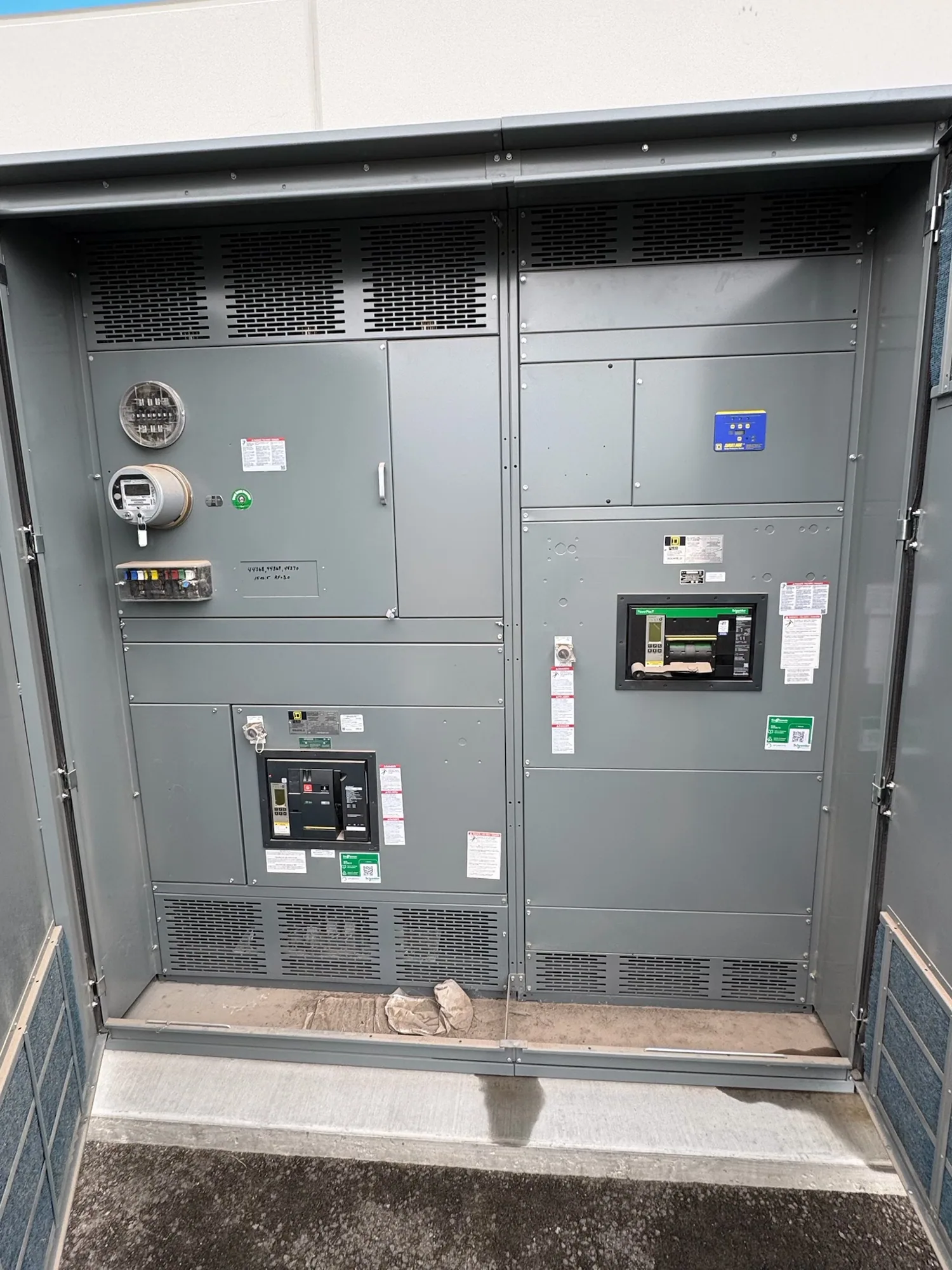
Coordinate sources around healthcare loads
In a healthcare facility, the generator-paralleling design must fit the engineered essential electrical system and the operating plan for the building. A project might involve multiple generators, utility service, transfer equipment, and distribution serving clinical and support loads. Paralleling switchgear coordinates generator sources when the design calls for them to operate together; it does not replace the project’s load classification, distribution design, or required transfer functions.
Begin with the responsible engineer’s one-line diagram and sequence of operation, not a generator count alone. Identify which sources connect to the paralleling lineup, what equipment transfers loads, and where downstream switchboards or other distribution assemblies begin. Clarify normal, emergency, and maintenance operating modes, including which loads remain supplied in each condition. The manufacturer can configure new equipment to a confirmed specification, while system design and approval remain with the project’s qualified engineering team.
Define the source sequence and control boundaries
Document how a generator is started, brought to the bus, and removed from service. If synchronization and closed-transition or other transfer behavior are part of the design, state the intended sequence and the equipment responsible for each action. Confirm whether sources may run in parallel with one another, whether utility paralleling is intended, and what permissives, interlocks, or operator actions apply. These are project decisions; they should not be inferred from a general product description.
Controls interfaces deserve particular attention in a hospital project. Identify connections to generator controls, transfer equipment, building management or supervisory systems, and any remote annunciation or monitoring specified by the engineer. Provide interface diagrams, signal lists, preferred control responsibilities, and the intended response to unavailable communications or an abnormal source condition. The scope should state which interfaces are included in the supplied assembly and which belong to other vendors or the site integration team.
Set load priorities and protection requirements
Give the design team a usable load schedule that distinguishes essential-system loads and other facility loads according to the project’s classifications. Note anticipated load steps, motor starting, additions planned for future phases, and any loads that may be shed or restored in a defined order. Ask the engineer to establish capacity and load-management criteria from the actual generator and facility data. Do not assume every connected load can be picked up simultaneously or that a particular sequence is appropriate for every hospital.
Protection and selective coordination should be addressed in the project documents where required. Provide available fault-current information, source and generator data, protective-device preferences, and the engineer’s coordination criteria. Confirm which devices and settings are within the switchgear scope and which depend on downstream equipment or field adjustments. A lineup’s protective arrangement must be evaluated as part of the system, not treated as a substitute for a coordinated study or the facility’s approved operating procedures.
Resolve voltage and equipment configuration
Specify nominal system voltage, phase and frequency, grounding method, and the system configuration shown on the one-line. Separately identify the required equipment voltage class and any maximum-voltage or insulation requirements established by the engineer. The nominal system value and the equipment’s maximum rating describe related but distinct design considerations; neither should be guessed from a building name or generator size. Confirm the selected product class and configuration against the actual project specification.
Also clarify bus arrangements, source and feeder quantities, incoming and outgoing connections, enclosure requirements, metering, control power, and space or cable-entry constraints. State environmental conditions and any special site requirements for the installation location. These details influence the physical lineup and interfaces, and late changes can affect drawings, procurement, and coordination with adjacent equipment. Listing, testing, ratings, and applicable standards must be confirmed for the specific proposed assembly; UL 891 applies to eligible low-voltage switchboards, not medium-voltage switchgear.
Plan continuity, outages, and safe handoffs
Continuity planning is a facility and engineering responsibility as well as an equipment-selection concern. Share the project’s phasing, existing-system interface points, outage windows, temporary-power assumptions, and restrictions on interrupting clinical operations. Identify who approves switching plans and who will verify the site is ready for delivery and installation. The equipment manufacturer can coordinate submittal information and supply scope, but should not be mistaken for the engineer, installer, commissioning provider, or facility operator.
Installation, inspection, testing, commissioning, and maintenance should be performed by qualified personnel under the applicable safety procedures. Specify what factory documentation or project records are required, and agree on review responsibilities and acceptance criteria before release. If field services are needed, establish them separately and confirm their availability and scope. No continuity plan should rely on an assumed procedure or on personnel working on energized equipment.
Prepare a complete equipment request
For a useful quotation, provide the one-line diagram, equipment schedule, sequence of operation, generator and source data, load schedule, protection criteria, and required controls interfaces. Include site and enclosure conditions, connection details, drawing and submittal requirements, desired project milestones, and the responsible contacts for engineering and procurement questions. Mark unresolved items clearly so the team can identify decisions that affect configuration rather than allowing assumptions to become part of the order.
South Carolina Switchgear Builders manufactures new switchgear and switchboards to specification, with US-built equipment and all-American components, and ships nationwide. Availability and actual lead times depend on the order and must be confirmed. Before purchase, review the proposed scope against the approved design, adjacent equipment, and project responsibilities. A clear specification and coordinated handoff help the healthcare team evaluate equipment that fits its intended source sequence and distribution plan.