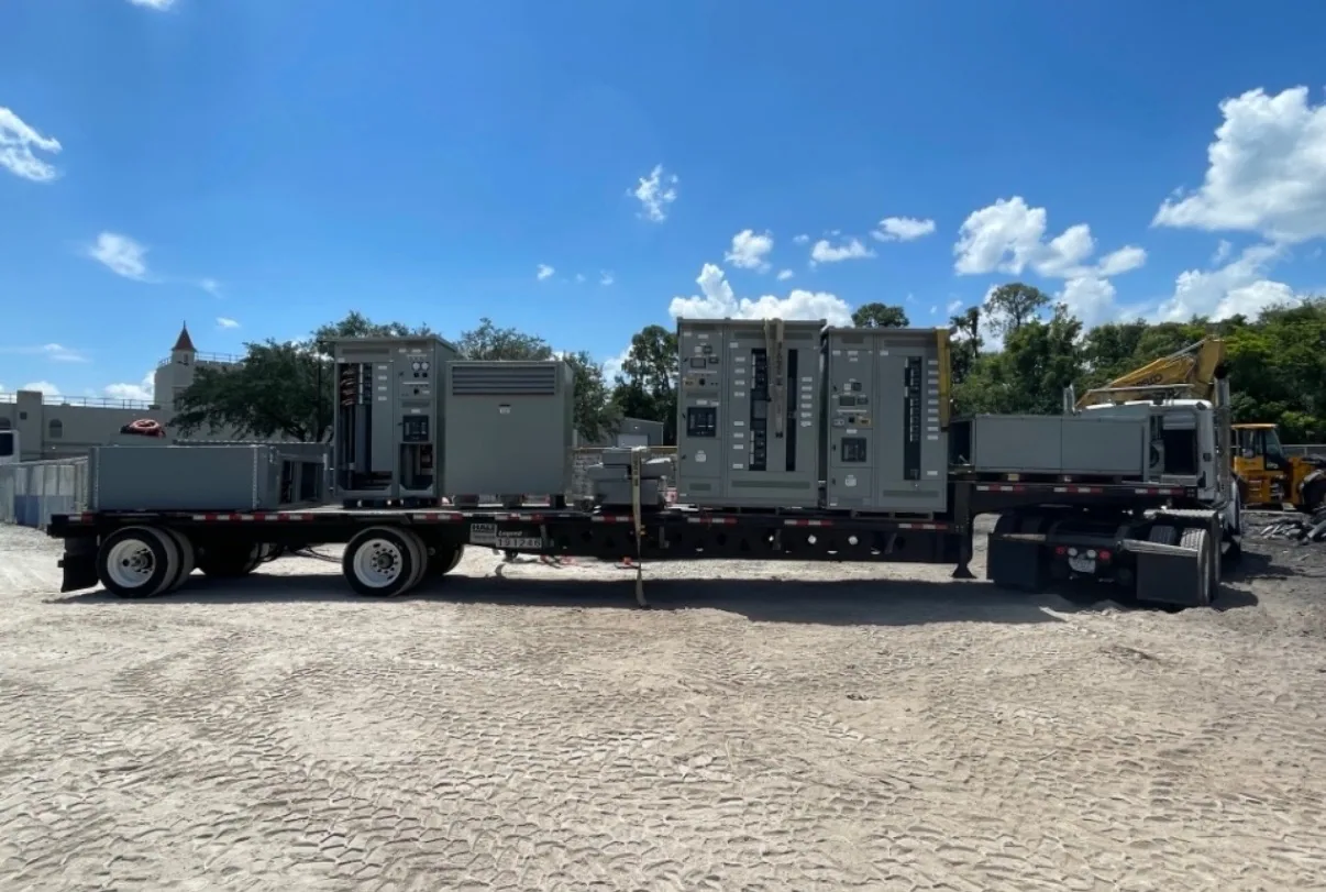
What generator paralleling switchgear does
Generator paralleling switchgear brings multiple generator sources together under coordinated control and connects their power to a distribution system. Depending on the design, it can support source connection, synchronization, protective functions, operating status and distribution to designated loads. The exact scope varies by project, so equipment should be specified around the intended operating sequence rather than selected by product name alone.
This equipment is distinct from an automatic transfer switch, which is generally used to transfer a load between sources according to its configured function. A generator paralleling system may coordinate several generators and manage their connection to a common bus; downstream switchboards, motor control centers and other distribution equipment serve different roles. The project engineer should define where each assembly begins and ends, and how control signals and power connections pass between them.
Start with the operating sequence
Describe what the system should do when utility power is available, when it fails, and when generator sources start or stop. Identify which generator starts first, whether units may connect as they become ready, how the system responds to a failed start, and what conditions permit reconnection to the normal source. These decisions establish control requirements and help prevent gaps between the intended sequence and the equipment scope.
Synchronization requirements need particular attention. The responsible engineer should specify how voltage, frequency and phase conditions are evaluated before a generator connects to a live bus, along with the permitted operating modes and interlocks. Confirm whether operators need local controls, remote supervisory commands or both, and identify which system has authority to issue commands. These details affect control interfaces, sequence documentation and coordination with generator packages.
Protection, load priorities and interfaces
Protection settings and devices must reflect the actual generator characteristics, system grounding, available fault information and connected distribution. Provide generator data and the project’s protection philosophy for review by the responsible electrical engineer. Confirm which protective functions are included in the paralleling equipment, which reside in generator controls or other assemblies, and how alarms, trips and status points are exchanged. No generic configuration can substitute for project-specific coordination.
Rank loads by operational importance and explain how they should be added, shed or restored as generation changes. A production process, for example, may have essential controls, large motor loads and noncritical support equipment with different restart needs. The engineer can use that hierarchy to assess load steps, generator capacity, sequencing and control interfaces. Planned expansion matters too: identify expected future sources or loads and distinguish firm requirements from possible later phases.
Match voltage and current requirements
State the system’s nominal voltage and frequency, grounding arrangement and phase configuration, and provide the generator and distribution data needed to verify compatibility. Equipment maximum voltage and insulation requirements are design considerations separate from nominal system voltage. A 480 V class assembly is low voltage; 5 kV and 15 kV class assemblies are medium voltage. Confirm the applicable class and complete ratings against the actual system specification.
Normal load current, generator output, bus capacity and individual device ratings all require review. Ask the engineer to account for operating conditions that could affect equipment selection, including ambient temperature, enclosure conditions and any applicable derating. Also provide available fault-current information and define the required short-circuit and protective-device coordination criteria. Ratings and design features must be confirmed for the specified assembly; they should not be assumed from voltage class or a general product description.
Balance continuity, complexity and future needs
More sources can support operating flexibility, but they also add coordination decisions: which units run together, how load is shared, how a unit is isolated, and what happens during maintenance or a fault. The appropriate arrangement depends on the required continuity, generator capabilities, facility operating plan and project budget. Ask the engineer to compare credible operating scenarios, including reduced generator availability and planned maintenance, rather than optimizing for only one normal condition.
Consider how operators will understand system state and respond to alarms. Control displays, remote monitoring and integration with building or facility systems may be relevant, but the needed points, protocols and command boundaries should be identified before design is finalized. Confirm who supplies generator controls, communications wiring and supervisory systems. Clear interface definitions reduce ambiguity among the switchgear supplier, generator provider, electrical contractor and controls integrator.
Prepare a useful equipment inquiry
For an initial equipment review, provide a single-line diagram, source and load schedules, generator manufacturer data, nominal voltage, frequency, grounding information and known fault-current values. Include the desired sequence of operation, priority loads, protection requirements, control and communications interfaces, installation environment, physical constraints and any expansion plans. Mark unresolved decisions clearly so the responsible engineer can identify what must be established before a final specification.
Also state project milestones, required submittal information, shipping destination and coordination contacts. South Carolina Switchgear Builders manufactures new switchgear and switchboards to specification, with US-built equipment and all-American components; availability and actual lead times depend on the order and must be confirmed. The supplier can review the requested scope, while the owner and engineer define system performance and the contractor plans installation and field coordination.
Coordinate scope through delivery
Before release, align the approved drawings, ratings, control narrative, interfaces and responsibility matrix among the owner, engineer, equipment supplier, generator provider and installing contractor. Confirm project-specific listing, testing, delivery dates and standards against the actual design and order rather than assuming they apply universally. Installation, testing and maintenance should be performed by qualified personnel under applicable safety procedures. A complete, coordinated specification gives the project team a sound basis for evaluating new generator paralleling equipment and carrying its requirements into procurement and installation.