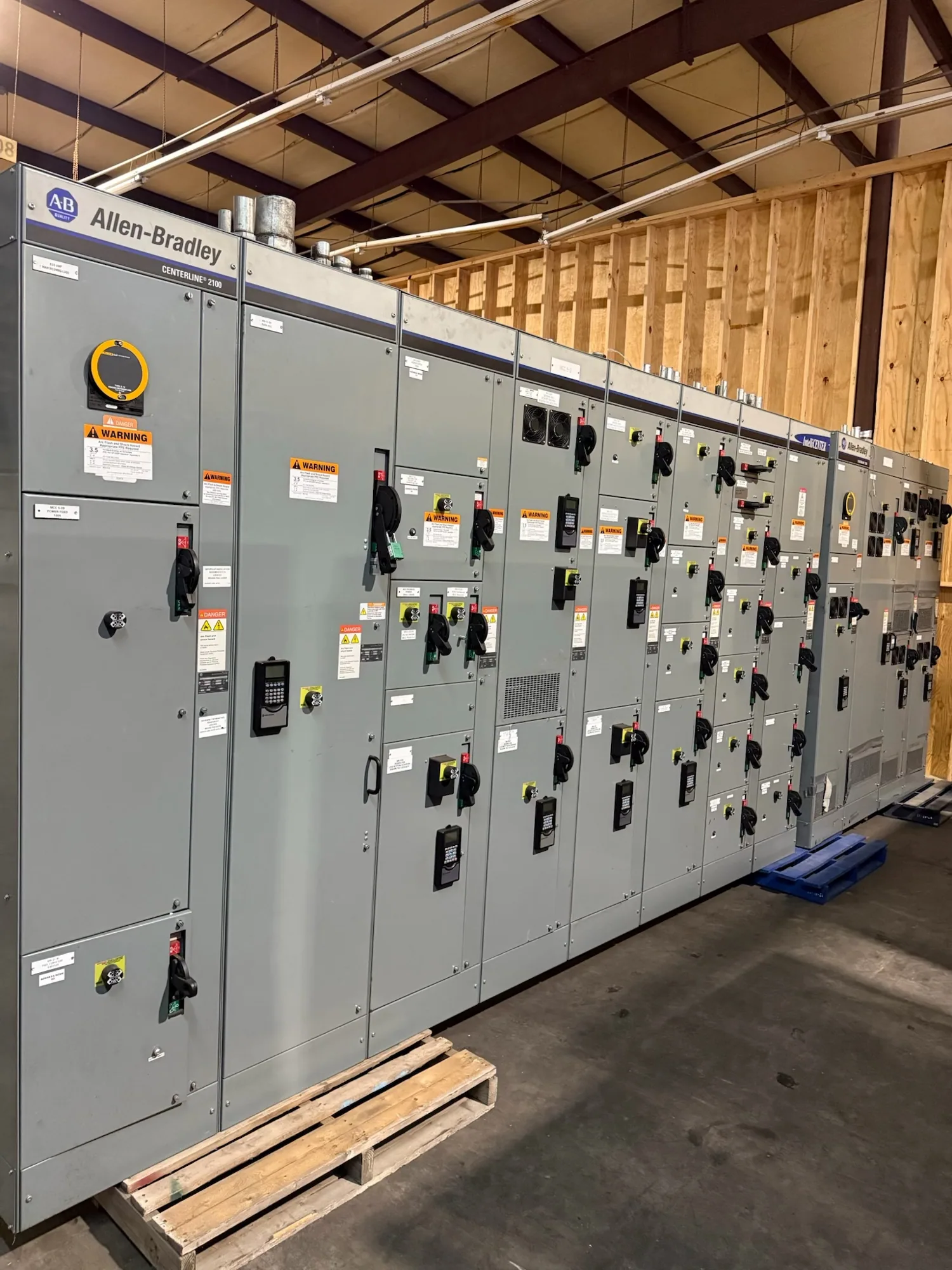
Start with the production distribution scope
Automotive manufacturing can bring together assembly equipment, welding processes, conveyors, paint operations, material handling, building systems, and control loads. A switchboard project should begin with the electrical distribution role it must perform—not simply a requested lineup size. Clarify whether the new assembly is intended for service distribution, a plant area, a production building, or a defined group of downstream feeders.
For a hypothetical plant upgrade, production may need to continue in unaffected areas while a distribution section is changed or expanded. Map the existing source, the loads served, and the boundaries of each planned outage. A new switchboard can be custom to specification, but the project team must establish the interface with existing equipment and determine how the installation will be sequenced.
Translate process loads into feeder organization
List major loads by process area and identify their electrical characteristics from responsible project documents. Include motor-driven production equipment, line controls, transformers, auxiliary systems, and any planned additions. The manufacturer needs to know which loads are served by each feeder and which groups require separate distribution. Do not assume that a broad label such as “production” conveys enough detail to define device selection or assembly layout.
Feeder segregation can make the intended operating boundaries clearer, but it should follow the plant’s actual one-line diagram, protection strategy, and outage plan. Ask whether equipment serving distinct line areas should occupy separate sections or compartments, and how cable entry, routing, and termination space affect that arrangement. The responsible engineer should confirm device coordination and operational requirements; a physical separation alone does not establish selective protection or uninterrupted operation.
Resolve current ratings from real operating conditions
Continuous current ratings should be evaluated against the expected load and the switchboard’s specified conditions—not selected from a single motor nameplate or a rough facility estimate. Provide the calculated demand, load schedules, diversity assumptions, operating profiles, and any applicable project criteria. Identify loads expected to run together, intermittent processes, and known future additions so the design basis reflects the way the plant will operate.
Bus and individual device ratings are related but serve different purposes. Confirm the required service and feeder ratings separately, along with applicable ambient or enclosure conditions that the responsible engineer expects the assembly to address. Temperature, grouping, ventilation, and other design details may affect selection; do not presume a rating or derating outcome without review of the actual specification. Ask the project engineer to document the assumptions and confirm the resulting requirements.
Coordinate fault duty, dimensions, and interfaces
Provide the available fault-current information at the proposed connection point and the project’s protection and coordination documents. The appropriate short-circuit rating and protective-device arrangement depend on the system and the specified assembly. These values cannot be safely inferred from a facility name, service size, or equipment model. The responsible engineering team should verify the required ratings and the compatibility of the proposed switchboard with upstream and downstream equipment.
Dimensions matter in active production buildings, where electrical rooms, cable pathways, access clearances, and delivery routes can constrain a lineup. Share room plans, allowable footprint, entry direction, conductor details, and constraints on removing or replacing existing gear. If work must occur during staged outages, identify the sequence and the boundaries of equipment that must remain in service. Qualified project personnel should plan installation and testing under applicable safety procedures.
Plan maintainability without promising continuity
Discuss how operators and maintenance teams expect to isolate feeders, access devices, and identify circuits. Clear circuit descriptions and a considered feeder arrangement can support routine work, but no switchboard configuration by itself guarantees uninterrupted production. Ask the project team to define which loads can be shut down, what isolation points are required, and whether the sequence for replacing or adding sections is practical for the facility.
Expansion planning also needs a defined basis. Identify anticipated process lines or load growth, the desired space or provisions, and the expected timing if known. Future capacity should be evaluated through load calculations, equipment ratings, physical dimensions, and project-specific design review; unassigned space does not automatically mean adequate electrical capacity. A realistic scope lets the manufacturer evaluate a new assembly against confirmed requirements rather than speculative allowances.
Prepare a useful purchasing package
For a quotation, assemble the one-line diagram, load schedules, source and fault-current data, requested continuous current ratings, device requirements, enclosure and dimensional constraints, cable-entry details, and applicable project specifications. Add the plant’s phasing plan, outage boundaries, delivery constraints, and expansion assumptions. Flag items that remain unresolved so the design team can distinguish firm requirements from questions requiring engineering confirmation.
South Carolina Switchgear Builders manufactures new switchboards in the United States using all-American components and ships nationwide. Builds are custom to specification; availability and actual lead times depend on the order and must be confirmed. Provide the requested standards and listing requirements for review against the specific assembly. UL 891 may apply to eligible low-voltage switchboards, but applicability and assembly listing must be verified for the proposed design.
Define responsibilities before release
Confirm who owns the electrical design, protection coordination, permit review, installation, field connections, commissioning, and acceptance testing. Manufacturer supply is not a substitute for those project responsibilities, and the scope should state which documents and equipment are included. Before approving a build, align the final drawings, ratings, interfaces, and delivery schedule with the responsible parties. That coordination gives purchasing and plant teams a clear basis for a switchboard suited to the production distribution plan.