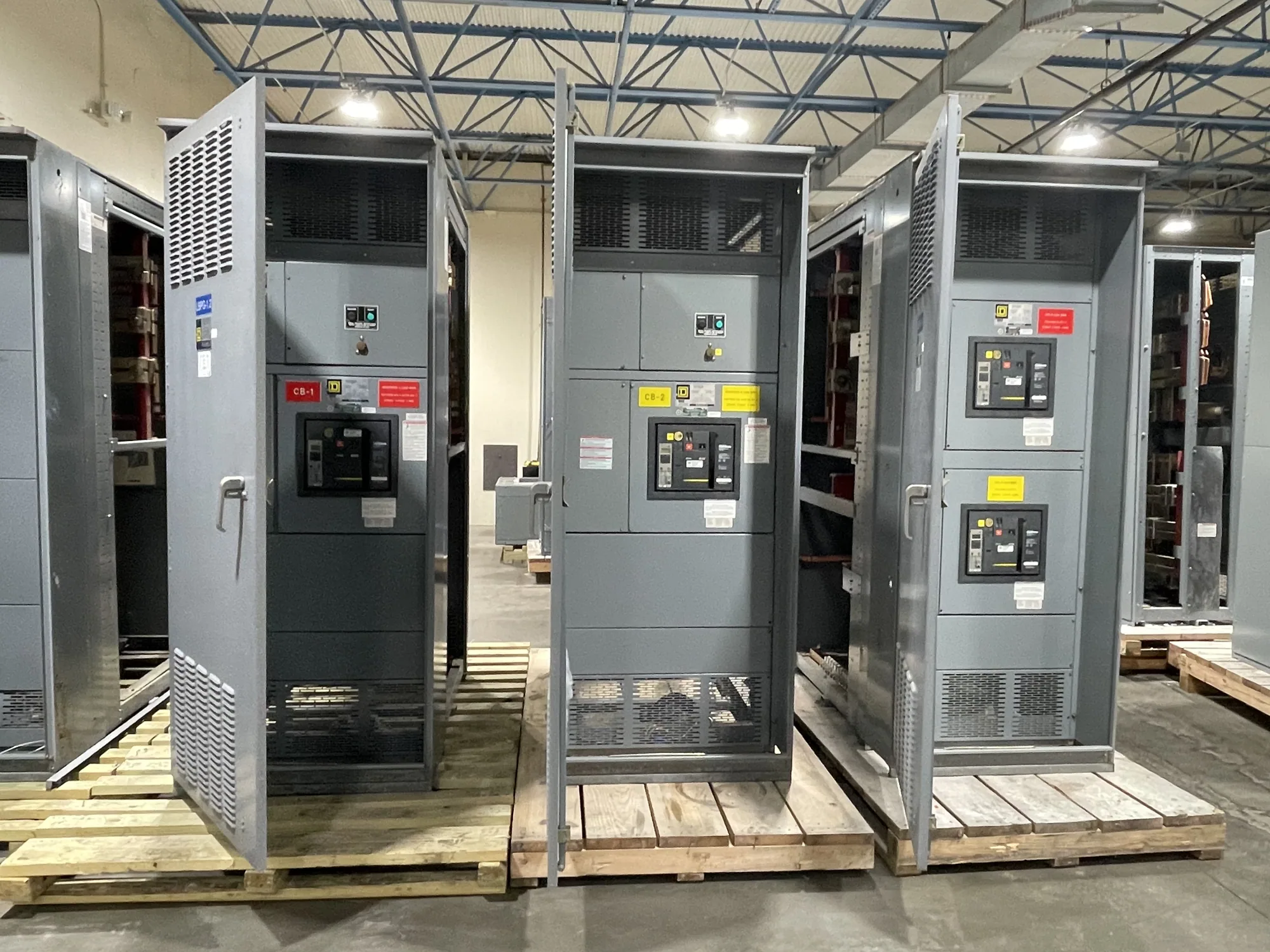
Where an MCC fits in a food and beverage facility
A motor control center (MCC) groups motor branch-circuit components and control equipment in a coordinated assembly. In a food or beverage plant, it may serve pumps, conveyors, mixers, compressors, packaging lines, or other motor-driven processes, depending on the project scope. It is not simply another name for switchgear: the equipment arrangement and functions should match the loads and distribution plan defined by the project engineer.
Consider a hypothetical facility with production equipment, refrigeration, washdown zones, and packaging machinery. These areas can impose different operating schedules, environmental conditions, and restart requirements. An MCC specification should identify which motors it serves, where the assembly will be located, and how operators and other equipment interact with it. This framing helps buyers assess a proposed configuration without assuming that one arrangement suits every plant.
Match motor control to process duty
Start with a motor schedule that identifies each load, its electrical characteristics, operating duty, starting method, and intended control interface. Depending on the application, a motor may use a starter or a variable-frequency drive (VFD); the responsible engineer should determine the appropriate method from process needs and equipment requirements. VFDs can affect heat dissipation, wiring, and coordination, so identify drive-provided equipment and any required interface details early.
Refrigeration and production loads may be important to facility continuity, but the MCC alone does not establish process resilience. Ask which loads must restart in sequence, which should remain isolated during maintenance, and what control or supervisory signals must be exchanged. The project team can then define feeder protection, branch-circuit devices, control wiring boundaries, and coordination with upstream distribution. Confirm each selection against the actual motor data and system design.
Account for washdown, sanitation, and heat
Washdown exposure is a location-specific design input, not a reason to assume that a standard enclosure is suitable. Document whether the MCC will be inside a production room, near a cleaning area, or in a separate electrical space. Describe moisture, cleaning practices, ambient conditions, airborne material, and the location of nearby process equipment. The project engineer and manufacturer can review enclosure and construction requirements against those conditions and the specified installation.
Sanitation interfaces also deserve deliberate planning. Consider equipment clearances, access for inspection, routes for conduit and control cables, and separation from cleaning or production activities. Drives and other components can contribute heat; operating temperature, enclosure arrangement, loading, and ventilation assumptions should therefore be reviewed together. Do not rely on a generic temperature or washdown claim. Provide the relevant room and process information so the proposed design can be checked for the specific application.
Resolve continuous current and device ratings
Continuous current rating is one part of selection, not a substitute for a complete load assessment. Provide normal operating current and available motor nameplate data, along with starting or drive information where applicable. The engineer must distinguish individual branch-device ratings, feeder requirements, and the MCC bus rating. These values serve different purposes; selecting an assembly from a single total-load figure can miss operating conditions or design constraints.
Ask how simultaneous operation, expected expansion, ambient temperature, enclosure conditions, and component arrangement affect the specified ratings. Any derating or adjustment must be based on the actual design and applicable equipment information, not an assumed rule. Identify motors that may be added later and whether spare spaces, capacity, or control provisions are desired. A future allowance is useful only when its intended scope is clear and compatible with the project design.
Plan for operation and continuity
Discuss how production staff will identify and control motor circuits, and how the MCC connects to plant automation or other control systems. Provide required control voltages, communication expectations, interlocks, alarm points, and ownership of field wiring. The responsible controls and electrical engineers should settle interface boundaries before release. Clear documentation reduces ambiguity between the assembly, process machinery, control panels, and field-installed conductors.
Also describe outage windows, access limitations, and the order in which equipment must be installed or placed in service. These constraints inform section layout, cable entry, shipping configuration, and coordination with site work. The manufacturer supplies the specified new assembly; engineering approval, installation, commissioning, and maintenance responsibilities should be assigned explicitly among the project parties. Installation and testing are for qualified personnel following applicable safety procedures.
Prepare a complete purchasing package
For a useful quotation, assemble the one-line diagram, motor schedule, load and control requirements, available fault-current information if established by the project, and the intended MCC location. Include environmental and sanitation conditions, requested enclosure details, system voltage, feeder and branch requirements, and any preferred starters or drives. Mark assumptions and unresolved items rather than treating them as confirmed design facts.
Identify delivery destination, access or shipping constraints, required submittal information, review milestones, and the project decision schedule. South Carolina Switchgear Builders manufactures new equipment to specification, with US-built equipment and all-American components; availability and actual lead times depend on the order and must be confirmed. Provide the complete application package for configuration review, then confirm ratings, construction, applicable listing, interfaces, and delivery details against the final approved specification before purchase.