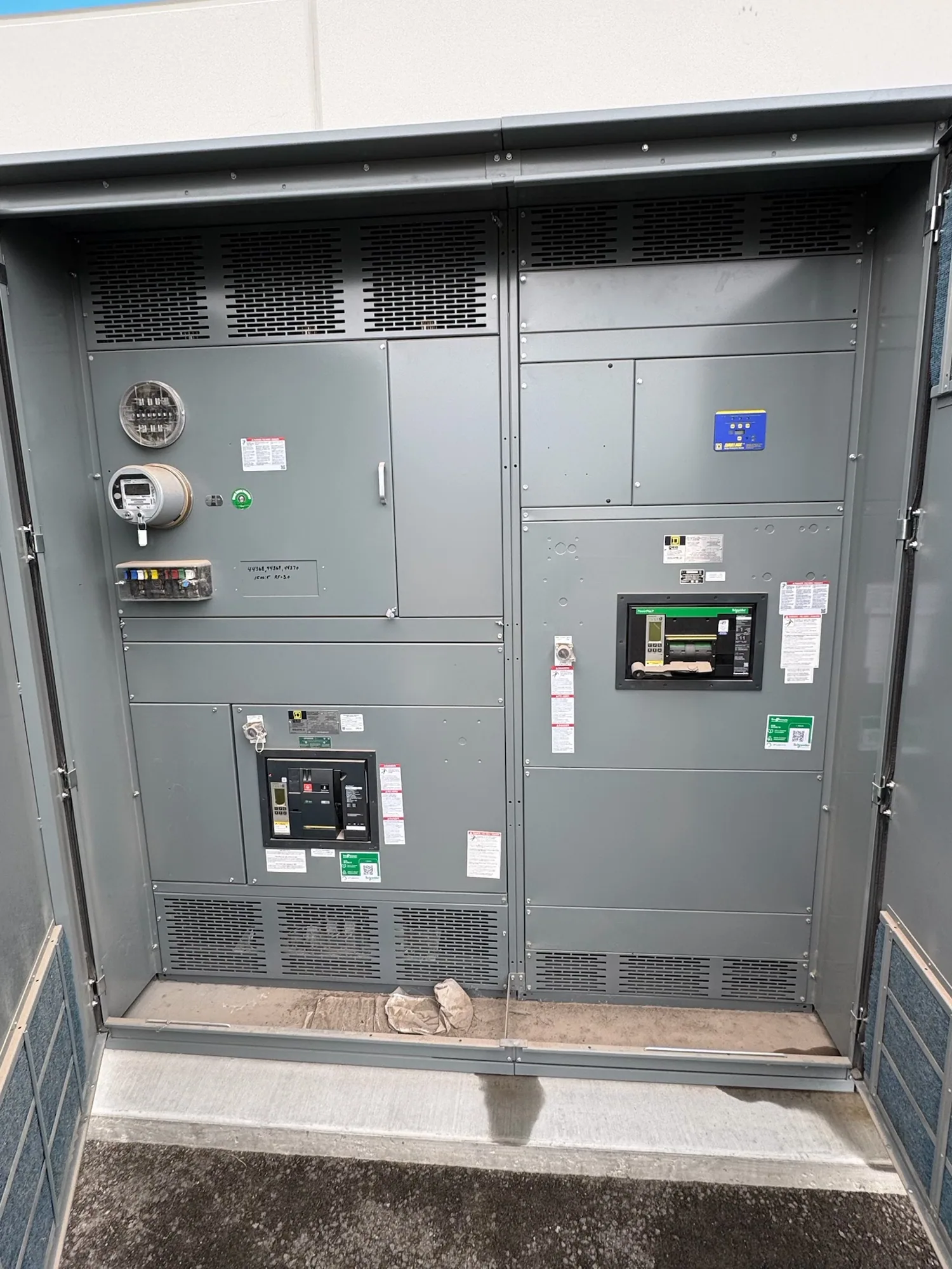
Start with the facility’s electrical duties
Food and beverage plants bring together loads with different operating patterns: process motors, refrigeration compressors, pumps, conveyors, packaging lines, lighting and building services. Their electrical distribution must support the actual equipment lineup and operating sequence, not a generic industry load profile. Begin with the one-line diagram, load list and planned operating modes, then identify which loads are essential to production or product protection.
For a new project or expansion, clarify whether the scope covers a service entrance, a main distribution point, a process area, or a replacement section within a larger system. Document the available supply, system voltage, fault-current information and connection requirements supplied by the responsible engineer or utility. These inputs establish the design basis; they should not be guessed from facility type or equipment nameplates alone.
Separate distribution from motor control
Medium-voltage switchgear may be considered where the project’s distribution architecture and supply voltage call for medium-voltage equipment. A low-voltage switchboard may instead serve downstream distribution, subject to the system design and specified voltage class. The two product categories are not interchangeable. Ask the project engineer to define where transformation occurs, what equipment belongs in each scope, and how protection and control interfaces connect across the system.
Large motors and refrigeration equipment can influence feeder sizing, protection coordination and operating plans. Confirm motor data, starting method, expected starts, duty cycle and any drives or control equipment that affect the electrical design. Switchgear is not a substitute for every motor-control function; determine whether starters, variable-frequency drives, controls or separate motor-control assemblies are furnished by others or included in the project package.
Address washdown and sanitation boundaries
Washdown areas create a practical coordination challenge because sanitation practices, moisture, cleaning chemicals and temperature conditions may vary by room and process. Locate electrical equipment according to the facility layout and the environmental conditions at its intended position. The buyer should provide exposure details and any enclosure or construction criteria established by the engineer. Do not assume that a general-purpose lineup is appropriate for every room or cleaning zone.
Coordinate equipment placement with hygienic design and cleaning procedures. Confirm access clearances, door swing, cable entry, floor conditions and the route for conduits or bus connections. The sanitation team and electrical designer should resolve how cleaning activity is separated from electrical equipment and whether barriers, remote placement or other measures are needed. Final suitability depends on the specified assembly and site conditions, not on an industry label alone.
Plan continuity around real operating priorities
Continuity means deciding what must remain available, what can be interrupted and how the system responds to maintenance or a fault. A refrigeration load protecting product may have a different operating priority from a packaging line that can pause between runs. Map those priorities with operations and engineering, then ask whether the distribution arrangement, spare provisions, protective devices and planned isolation points support the intended operating strategy.
Redundancy is not automatically beneficial: it can add equipment, footprint, coordination work and operating complexity. Conversely, a simple arrangement may not satisfy the facility’s interruption limits. State the required operating scenarios and ask the responsible engineer to evaluate them against the proposed design. Any transfer scheme, alternate source, selective coordination objective or maintainability feature must be defined and confirmed for the actual system.
Specify continuous current and environmental conditions
Continuous current ratings should be selected from the system requirements and the specific assembly configuration. Provide normal load current, expected continuous loading, feeder and bus requirements, and the ratings of connected devices. The bus and individual devices may have separate rating considerations. The project engineer should reconcile these values with the one-line diagram and the equipment schedule rather than choosing a rating from peak production demand alone.
Ask how operating temperature, enclosure conditions, ventilation, installation location and any specified derating factors affect the proposed configuration. Those conditions can change the usable capacity or design choices, but the answer depends on the equipment and project specification. Confirm applicable ratings and any listing or testing requirements for the specific assembly. UL 891 may apply to eligible low-voltage switchboards; applicability and assembly listing must be verified, and it does not establish requirements for medium-voltage switchgear.
Prepare a useful equipment inquiry
A focused inquiry should include the one-line diagram, voltage class, available fault-current data, load and motor schedules, normal and emergency operating modes, and requested continuous-current ratings. Add site conditions such as ambient temperature, washdown exposure, room dimensions, access constraints and cable entry preferences. Identify required protective devices, metering, controls, communications interfaces and scope boundaries, while marking items that remain subject to engineering review.
Include the project location, desired shipment window and purchasing or submittal milestones. Availability and actual lead times depend on the order and must be confirmed. South Carolina Switchgear Builders manufactures new equipment to specification, with US-built equipment and all-American components, and ships nationwide. Confirm the proposed configuration, delivery dates, ratings, testing, listing and standards against the final specification before release. The project team should coordinate installation and acceptance activities with qualified personnel using applicable safety procedures.