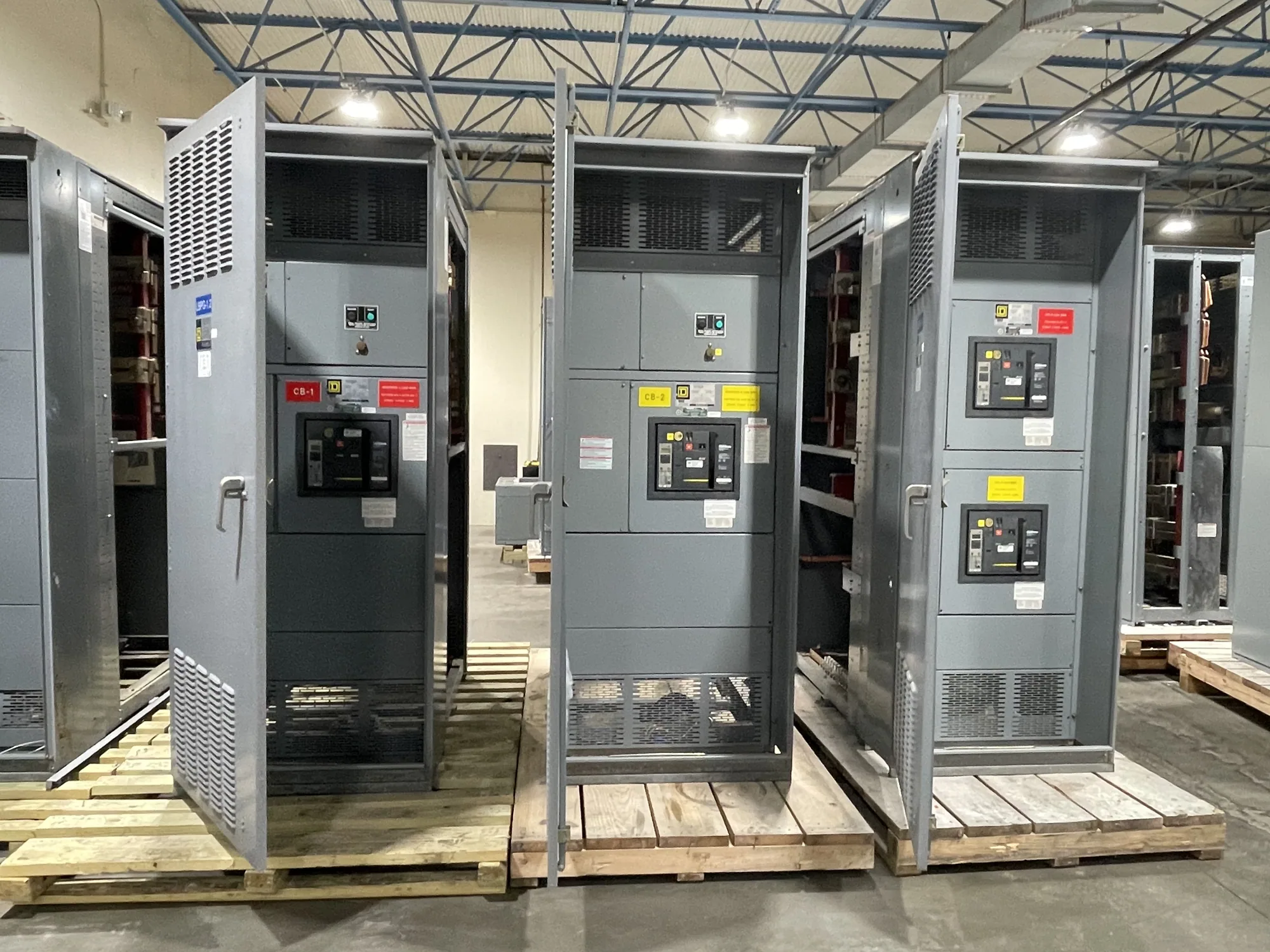
Where medium-voltage switchgear fits — Medium-Voltage Switchgear for South Carolina
Medium-voltage switchgear is used in distribution systems where incoming power or feeders operate in a medium-voltage class. It can support source distribution, feeder control and protection, and connections serving downstream equipment. The exact lineup depends on the electrical system and project requirements; product configuration, availability, ratings and applicable standards must be confirmed against the specific design.
It is important to distinguish switchgear from adjacent equipment. Low-voltage switchboards serve different voltage classes and functions, while higher-voltage equipment requires its own specification and design review. A project’s nominal voltage alone does not settle equipment selection. The responsible engineer must verify the system voltage, equipment maximum voltage, insulation requirements and intended application before a manufacturer prepares a proposal.
Establish voltage and insulation requirements
Begin with the system’s nominal voltage and the required equipment voltage class, then confirm the maximum voltage and insulation level specified for the application. These values should be coordinated with the source, connected equipment and project design documents. Do not select equipment by a broad label alone: the actual system configuration and applicable engineering requirements determine which design is suitable.
Insulation and isolation are related but distinct considerations. Insulation supports the required separation between energized parts and grounded or adjacent components; isolation requirements concern how equipment is arranged and operated within the system. Ask the project engineer to define required clearances, switching functions, grounding provisions and access expectations. Environmental conditions and operating temperature may also affect design or rating, so provide the conditions the equipment will encounter rather than assuming a standard indoor environment.
Coordinate current ratings and operating conditions
Specify expected normal load current and the required ratings for bus and switching devices. These values should reflect the actual feeder arrangement and anticipated operating duty, not just a single connected-load estimate. Where loads may be added, discuss the intended expansion plan early. Extra capacity can influence lineup dimensions, device selection and project cost, while oversizing without a defined need may add complexity.
Ask how site conditions affect applicable ratings. Ambient temperature, enclosure arrangement, ventilation and other installation conditions may require engineering review or derating. Confirm the required interrupting and withstand capabilities from the project’s system study and design documents; do not infer them from voltage class or normal current. The responsible engineer should establish system fault conditions and protective coordination requirements for the manufacturer to address in the specified design.
Plan protection, control and relay interfaces
Protective-relay interfaces should be defined alongside the switching arrangement. Identify the required protection functions, instrument-transformer inputs, control power, trip and close circuits, alarms, communications and interface points, as applicable to the project. The owner’s engineer should state which functions are required and how they coordinate with upstream and downstream devices. Manufacturer scope, wiring boundaries and any supplied components need confirmation in the quotation and approved drawings.
For example, a production facility with medium-voltage feeders serving motor loads may need to coordinate feeder protection with process continuity and planned line expansion. The design team should clarify which motors are supplied at medium voltage, what starting or operating characteristics matter, and whether future feeders are anticipated. This scenario is a planning example, not a universal configuration; the project engineer must determine the required switching, protection and ratings.
Prepare a useful equipment specification
A focused request for quotation helps reduce avoidable assumptions. Provide the one-line diagram, nominal and maximum system voltage, frequency, grounding method, source and feeder arrangement, normal load current, bus and device ratings, and available fault-study information. Include the applicable insulation requirements, enclosure and installation conditions, operating temperature, control voltage, relay functions, communications interfaces and desired future provisions.
- Identify the project location and indoor or outdoor installation conditions.
- Share relevant drawings, load data, protection requirements and interface responsibilities.
- State required equipment scope, documentation, inspection or testing expectations for confirmation.
- Flag schedule needs and delivery constraints without assuming a guaranteed date.
Also identify who will approve protection settings, drawings, field connections and commissioning procedures. The manufacturer can develop equipment to specification, but the owner, engineer and installing contractor retain project-specific design, installation and operational responsibilities according to their scopes. Testing and maintenance belong to qualified personnel following applicable safety procedures.
Review scope and coordinate the purchase
South Carolina Switchgear Builders manufactures new switchgear in the United States using all-American components and ships nationwide. Custom configurations and short lead times are part of the offering, but the proposed design, availability and delivery timing require confirmation for each project. Ask for a proposal that clearly states the equipment scope, design assumptions, ratings, exclusions, submittal process and any project-specific listing or testing requirements.
Before release, compare the proposal with the approved one-line diagram and specification, and resolve open points with the engineer and contractor. Confirm that each required interface, rating and responsibility is documented. A clear, coordinated specification gives the manufacturer a sound basis for preparing medium-voltage switchgear for the project and helps the buying team evaluate the equipment against its actual distribution needs.