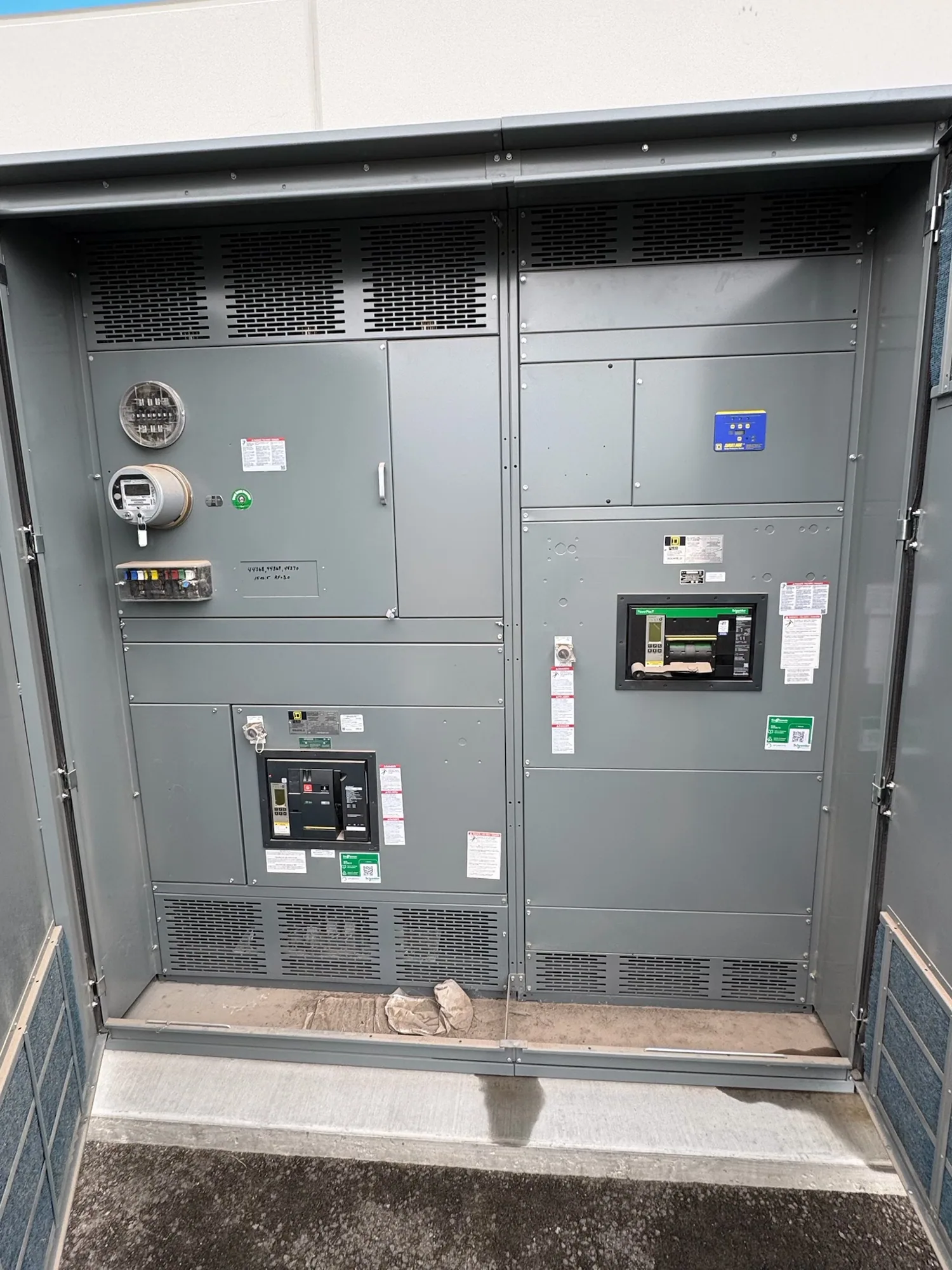
What metal-enclosed describes
Metal-enclosed switchgear places electrical switching and protection equipment within a metal enclosure. That description alone does not establish the construction class, electrical ratings, switching method, or suitability for a particular system. Depending on the design, the assembly may contain switches, circuit breakers, fuses, bus, and cable connections in different arrangements. Buyers should identify the required equipment category and functions before comparing proposed lineups.
Metal-clad switchgear is a more specifically defined type of metal-enclosed switchgear. Its construction requirements include designated compartment separation and removable main switching devices, as defined by the applicable requirements. A lineup is not automatically metal-clad simply because it has a metal exterior or internal partitions. Likewise, a metal enclosure alone does not establish an arc-resistant design or an outdoor enclosure rating. Ask the engineer to define the construction required for the application and verify the proposed assembly against it.
Match switching and protection to circuit duties
Start with a one-line diagram showing the incoming source, main devices, bus, and outgoing circuits. Identify what each circuit supplies and whether its purpose includes switching, fault protection, isolation, or a combination of functions. A fused-switch arrangement and a circuit-breaker arrangement are not interchangeable by name alone. Their capabilities, protection schemes, and maintenance implications must be assessed for the actual circuit and equipment design.
Discuss required interlocks, indication, metering, control power, and remote status or control interfaces where relevant. The owner and engineer should describe the intended operating philosophy, while the manufacturer confirms what the proposed configuration includes. Do not assume that a visible handle, a closed door, or an interlock provides every isolation or safety function the project needs. Installation, operation, and maintenance belong to qualified personnel following applicable procedures.
Establish the electrical design basis
Provide the nominal system voltage, system configuration, frequency, and grounding method. The responsible engineer must determine the required equipment maximum voltage and insulation characteristics for the application; nominal system voltage by itself is not a complete equipment specification. Identify the source arrangement and connected equipment so the proposed design can be assessed as part of the wider distribution system.
Normal load current, bus and device current ratings, available fault current, interrupting duty, and short-circuit withstand requirements are separate considerations. Share the available studies and intended operating conditions with the design team rather than assuming that one published rating covers the entire lineup. Ambient temperature, ventilation, and other installation conditions may affect applicable ratings or require derating. The engineer must confirm all application-specific design choices and ratings against the actual assembly.
Plan the enclosure and physical interfaces
Tell the project team whether the equipment is intended for an indoor room or an outdoor location, and describe conditions such as moisture, airborne contaminants, temperature, and exposure to corrosive substances. The selected enclosure and its documented suitability must match the actual environment; metal construction alone is not proof of weather protection or corrosion resistance. Ventilation requirements and the surrounding space also deserve review because they can influence both equipment layout and operating conditions.
Coordinate cable entry, termination space, lifting and shipping splits, foundation or mounting interfaces, and access for inspection or device replacement. Door swing and removable-device handling can affect the footprint beyond the enclosure itself. Specify the grounding and bonding interfaces for the lineup and coordinate them with the facility grounding design. Required clearances, access arrangements, and connections must be confirmed by the engineer and installing contractor for the chosen equipment.
Consider a production-line expansion
Imagine a manufacturing facility planning new distribution equipment for several production lines, including feeders serving motor loads. The design team might compare circuit arrangements based on which loads need separate protection, how planned shutdowns affect production, and what switching functions operators need. Motor starting characteristics and the coordination of protective devices can influence the design; neither the enclosure name nor a feeder count resolves those questions.
If another line may be added later, the owner should describe its anticipated load and timing rather than simply asking for room to grow. A reserved section, provision for a future feeder, and unused physical space are different things. The engineer and manufacturer should identify which electrical and mechanical provisions are included now, what remains subject to future review, and how each choice affects the present layout and project scope.
Prepare an inquiry for new equipment
An inquiry is more useful when it includes the latest one-line diagram, load information, fault-study data, required switching and protection functions, site conditions, and the preferred cable and control interfaces. Include the intended equipment construction class, required documentation, inspection or testing expectations, and any applicable project-specific listing or standards requirements. Clearly mark missing inputs so the responsible engineer can resolve them before the design is finalized.
South Carolina Switchgear Builders supplies US-built custom new gear using all-American components and ships nationwide. Confirm availability of the specific metal-enclosed construction and configuration, along with the proposed scope, applicable ratings, testing, and any listing, for the order. The owner defines operational needs, the engineer confirms the system design, the contractor coordinates site installation, and the manufacturer confirms the equipment it will provide. An agreed scope and reviewed drawings give each party a clearer basis for moving the project forward.