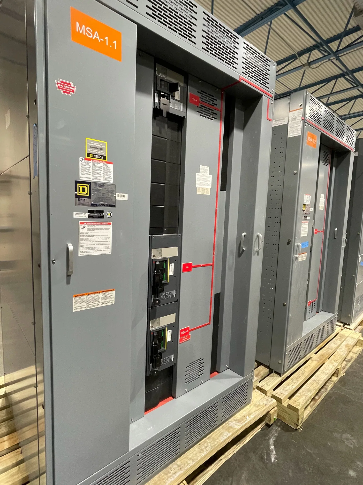
Where low-voltage switchgear fits in aerospace production
Aerospace manufacturing facilities may bring precision production equipment, test systems, environmental controls, and process support loads together on one site. A low-voltage switchgear assembly can distribute power to defined parts of that operation and provide protective devices for connected circuits. The useful starting point is not a generic industry package; it is understanding which loads the assembly will serve and how the facility expects to operate.
For a project involving a new production area, a replacement distribution point, or a planned capacity change, map the equipment and its supply boundaries. Identify which loads are essential to a process, which can tolerate interruption, and which have separate sources or controls. The responsible electrical engineer should determine the system architecture and applicable ratings. The manufacturer can then evaluate a new assembly configured to the project specification.
Match protection to the actual electrical system
Interrupting and withstand ratings address different system conditions and should be reviewed against the available fault current and the specified protection scheme. A device's interrupting rating must suit the conditions at its point of application; the assembly's withstand capability must be evaluated for the specified duration and configuration. The project engineer should establish these values from system studies and confirm that the proposed equipment is suitable.
Protection coordination matters where an interruption could affect more than the immediate faulted circuit. Review upstream and downstream protective devices, settings, and operating objectives with the engineer responsible for the facility. Selectivity cannot be assumed from the equipment category alone. Provide any coordination study requirements, device preferences, or existing system information early so the equipment design can be checked against the intended scheme before release.
Plan for process continuity, access, and phased changes
In quality-sensitive production, an electrical interruption may affect more than a single machine. Discuss which operations must stop together, which require orderly shutdown, and whether test equipment or environmental support has special continuity needs. These are project requirements to document, not grounds for assuming that switchgear by itself prevents interruptions. The facility's design team should define operating priorities and any separate continuity measures.
Space and maintainability also shape the design. Provide room dimensions, access routes, door and handling constraints, cable entry direction, and nearby equipment clearances for review. Explain whether future sections or circuit additions are planned and how phased construction will interact with existing distribution. The project team should identify outage windows, tie-in boundaries, and responsibilities for field work; equipment supply does not itself include installation or facility engineering.
Resolve continuous-current ratings from real operating conditions
Continuous-current selection starts with the expected normal load, not simply the sum of equipment nameplate values. Provide load schedules, demand assumptions, diversity or operating scenarios, and any known near-term additions. The engineer should determine the required bus and protective-device current ratings, considering how loads may operate simultaneously and whether the assembly serves a single process area or multiple production functions.
Ask how ambient temperature, enclosure arrangement, ventilation, conductor layout, and equipment grouping affect the specified design. Applicable derating conditions and operating temperature must be evaluated for the actual assembly and installation environment; do not infer them from a nominal current value. Confirm the required ratings and any project-specific design criteria with the responsible engineer and manufacturer before finalizing the equipment schedule.
Information to include in an equipment request
A useful inquiry identifies the application, project stage, requested quantity, delivery destination, and target schedule, while making clear that dates depend on order details and must be confirmed. Include the one-line diagram, system voltage, available fault-current information, load schedule, protection requirements, and any relevant study findings. If a document is preliminary or values remain open, label them clearly rather than presenting estimates as approved design data.
Also provide layout drawings, enclosure and access constraints, cable entry preferences, environmental conditions, interface requirements, and the intended phase plan. Note any preferred devices or controls, but distinguish mandatory requirements from acceptable alternatives. For a new assembly, the specification should state which documents, drawings, and project reviews are expected. These details help identify design questions and support a quote that reflects the intended scope.
Coordinate supply, engineering, and installation responsibilities
South Carolina Switchgear Builders manufactures new low-voltage switchgear and supplies equipment for projects in South Carolina and nationwide. Configurations are custom to specification; availability and actual lead times depend on the order and should be confirmed. Project-specific ratings, listing applicability, testing, delivery dates, and standards require verification against the actual design and supplied equipment. UL 891 applies to eligible low-voltage switchboards; applicability and assembly listing must be confirmed for the specific design.
Before purchase, establish who owns system studies, final design approval, protection settings, installation, field testing, and commissioning. Those responsibilities typically involve the facility's qualified electrical professionals and other appointed project parties; they should not be assumed as part of equipment manufacture. When scope, ratings, interfaces, and schedule are documented, the manufacturer can review the request and identify information still needed to define a suitable new switchgear assembly for the aerospace manufacturing project.