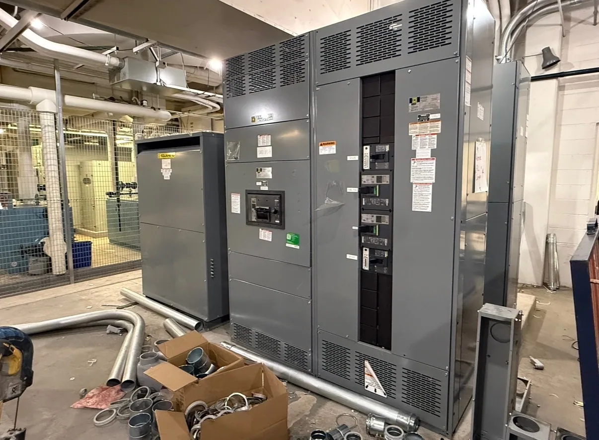
Where metal-clad switchgear fits in a data center
Data centers combine concentrated IT demand with substantial cooling, supporting systems, and often multiple power sources. Medium-voltage metal-clad switchgear may be considered where the project distribution design calls for switching and protection at that part of the system. Its role depends on the electrical one-line diagram and the boundaries between utility service, transformers, backup generation, and downstream distribution equipment.
Metal-clad construction uses separated compartments and removable switching devices, subject to the specified design. For a data center, those features can inform how equipment access, inspection, and maintenance are planned. They do not by themselves establish redundancy, uptime, fault performance, or suitability for a particular room. The project engineer must define the operating arrangement and confirm each assembly against the intended application.
Coordinate sources, loads, and operating modes
Begin with the normal and alternate source arrangements, including how the system is intended to respond to a source loss or planned outage. Identify whether utility feeds, generators, transformers, or other sources connect at the metal-clad lineup, and clarify which switching and protective functions belong there. The exact scheme, interlocking, and transfer responsibilities require project-specific engineering and confirmation with the responsible parties.
Map the major load groups served downstream: IT distribution, cooling plants, pumps, and other essential or nonessential loads. Distinguish present demand from planned capacity phases, and explain how additions are expected to connect. A lineup layout that anticipates future sections may affect dimensions, bus arrangement, protection interfaces, and coordination. The manufacturer needs the actual requirements; future expansion should not be assumed to be accommodated without design review.
Understand compartmentalization and maintainability
Compartmentalization and removable devices can support defined access and equipment replacement strategies, but the benefits depend on the selected construction and operating procedures. Ask which components are removable, what isolation boundaries are provided, and what clearances and access the installation requires. Consider room layout, cable entry, front or rear access needs, and how qualified personnel will work under the applicable safety procedures.
Data center outage constraints should shape the specification early. Describe the maintenance windows, switching restrictions, and acceptable equipment boundaries for planned work. Do not treat a compartmentalized lineup as permission for energized work or as a guarantee that a load can remain served during maintenance. Qualified personnel and the project’s approved procedures govern installation, testing, operation, and maintenance.
Resolve voltage and protection requirements
Provide the nominal system voltage and ask the project engineer to identify the required equipment maximum voltage, insulation level, and system configuration. These are related but distinct specification items; a nominal voltage alone does not define the complete equipment requirement. Confirm whether the system is grounded and how that affects the specified design, and document the available source and downstream connection information requested by the responsible engineer.
Protection coordination should account for the sources and loads that can contribute under each intended operating mode. Supply the available fault-current information and protective-device requirements established for the project, along with any relay functions, metering, communications, or alarm interfaces in scope. Do not assume settings, ratings, or coordination outcomes from a general product description. The responsible engineer must establish the criteria, and the proposed equipment must be checked against them.
Plan monitoring and controls at the interfaces
List the information operators need to monitor and where it must be delivered, such as local indication, control-system points, or communications interfaces. Identify the required signals, protocols, control authority, and points of connection rather than relying on a general request for “remote monitoring.” Clarify whether controls and communications are part of the equipment supply or provided by another project team.
Also document the control power source, interlocking requirements, and interfaces with generators, transfer equipment, or building systems where applicable. Assign responsibility for drawings, point lists, network coordination, and functional verification. These details affect engineering and procurement coordination, but their inclusion does not establish compatibility until the specific devices and interfaces are reviewed.
Prepare a useful purchasing scope
For a quote, provide the one-line diagram and equipment schedule, nominal voltage, required equipment ratings, source configuration, bus and feeder arrangement, protection and metering scope, and relevant control interfaces. Include environmental and installation constraints, cable-entry preferences, access limitations, and the anticipated phasing plan. Note which requirements are settled and which remain subject to engineering review, so open items are visible rather than mistaken for confirmed selections.
South Carolina Switchgear Builders manufactures and supplies new equipment, including custom-to-specification switchgear, with US-built equipment and all-American components. Availability and actual lead times depend on the order and must be confirmed. Nationwide shipping is available; delivery dates and the exact scope require project review. The manufacturer’s equipment supply is distinct from system studies, engineering approval, installation, field testing, and maintenance, which should be assigned to the qualified project teams.
Coordinate decisions before release
Before procurement, align the equipment specification with the engineer of record, owner, electrical contractor, utility or source providers as applicable, and controls team. Confirm drawing review responsibilities, submittal expectations, approved deviations, and how changes to load phases or source arrangements will be handled. Final ratings, construction, listing applicability, and delivery commitments must be confirmed for the actual design and order.
A clear, coordinated scope helps the manufacturer evaluate the intended lineup and identify information still needed. It also gives the data center team a basis to compare proposals without treating generic descriptions as design approval. Resolve technical questions through the responsible project professionals, then confirm the equipment configuration and schedule before release.