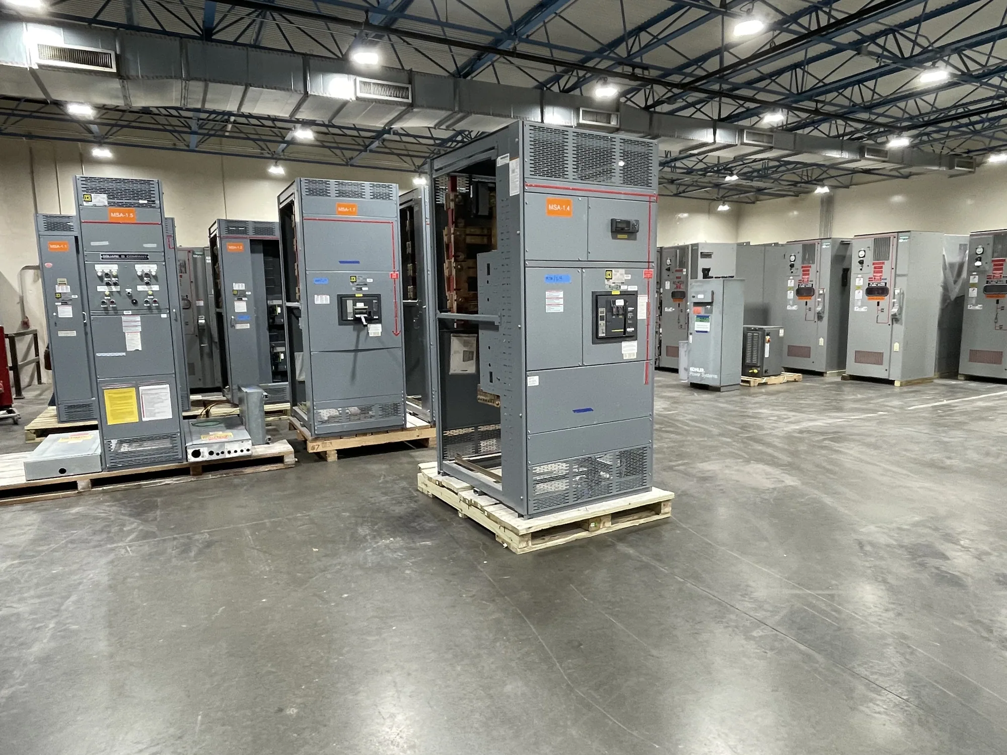
Map production needs before selecting equipment
Automotive manufacturing distribution must serve more than a single building load. Production lines, robotic cells, presses, conveyors, paint operations, utilities, and facility systems can have different operating schedules and consequences when interrupted. Start by identifying which loads must remain available, which can stop together, and which planned expansions may change the distribution arrangement. The right equipment configuration depends on the facility’s actual electrical system and operating priorities.
Develop a one-line diagram and load information with the responsible electrical engineer. Include source characteristics, existing distribution interfaces, feeder destinations, motor and other significant loads, and known operating sequences. Identify whether a project is new construction, a production-line addition, or replacement within an operating plant. That context helps the manufacturer evaluate equipment scope and helps the project team coordinate design, procurement, and installation assumptions.
Plan distribution around outages and segregation
Where production cannot stop as a single block, consider how feeders are grouped and whether distinct process areas need separately arranged distribution. Segregation can help limit the area affected by planned work or an electrical event, but it also introduces design choices about sources, protective devices, space, and operational procedures. Confirm the intended boundaries with plant operations and engineering; equipment alone cannot guarantee continuity or determine how a facility should be operated.
For work in an active plant, identify the installation window and the interfaces that must be completed before an outage begins. Review access routes, equipment placement, cable entry, termination requirements, and the sequence for removing or connecting distribution sections. The project team should establish responsibilities for drawings, field verification, shutdown planning, testing, and turnover. Installation, testing, and maintenance must be performed by qualified personnel under applicable safety procedures.
Choose a voltage class and equipment scope
Low-voltage switchgear may be appropriate for distribution at a 480 V class where the project’s source, loads, and system design support that choice. Medium-voltage switchgear may be considered for distribution at 5 kV or 15 kV class when the electrical design calls for that equipment. These are not interchangeable labels: voltage class, equipment function, and interface requirements need to match the project documents and be confirmed by the responsible engineer.
Clarify whether the required product is switchgear or a low-voltage switchboard, and define what belongs in the equipment package. Depending on the specification, relevant scope questions may include incoming and outgoing sections, metering, protective devices, control wiring, and provisions for future feeders. UL 891 applies to eligible low-voltage switchboards; whether it applies, and whether a specific assembly is listed, must be verified for that design. It does not apply to medium-voltage switchgear.
Match continuous-current ratings to real conditions
Continuous-current selection begins with the expected load, but the normal operating current is not the only consideration. The engineer should evaluate bus and device current ratings, load growth, operating cycles, simultaneous demand, and the project’s specified ambient and enclosure conditions. A rating that looks adequate from a basic load total may need further review if the equipment will operate under conditions that affect its permitted continuous performance.
Ask how temperature, ventilation, enclosure arrangement, conductor terminations, and any specified derating conditions affect the proposed configuration. Do not assume that a single current figure describes every bus section or device, or that all components have identical ratings. The applicable values and limitations must be checked against the actual equipment design and specification. Confirming these details early can prevent mismatched expectations between engineering documents, purchasing scope, and the supplied assembly.
Allow for maintainability and planned expansion
Production growth can change feeder count, loading, and the physical space available for distribution. Tell the equipment manufacturer which future loads are reasonably anticipated and whether the project requires spare or reserved provisions. Additional capacity or sections can affect footprint, cost, coordination, and installation planning, so distinguish firm requirements from options. Confirm that any proposed provision is compatible with the selected design rather than assuming later expansion will be automatic.
Review working clearances, room access, cable routing, identification, and the intended maintenance approach with the project team. A maintainable arrangement should reflect the facility’s operating procedures and qualified personnel’s access needs, not just fit on a drawing. Discuss how feeder labels and documentation will correspond to production areas and equipment. These practical details can support clearer turnover and reduce ambiguity when operations staff plan future shutdowns or distribution changes.
Prepare a focused equipment inquiry
Before requesting a proposal, assemble the one-line diagram, project location, voltage class, available source information, load and feeder schedule, and required current ratings. Add the equipment scope, applicable specifications, enclosure and environmental conditions, physical constraints, and any project requirements for testing or listing. Identify the required ship-to point and target project milestones. Availability and actual lead times depend on the order and must be confirmed.
Ask the project owner, engineer, and purchasing team to resolve open questions together: Which loads are production-critical? What outage sequence is feasible? What future feeders are planned? Which standards and documentation apply to this particular assembly? South Carolina Switchgear Builders manufactures new US-built equipment with all-American components, custom to specification, and ships nationwide. Share the confirmed requirements to begin evaluating a suitable scope, configuration, and schedule for the project.