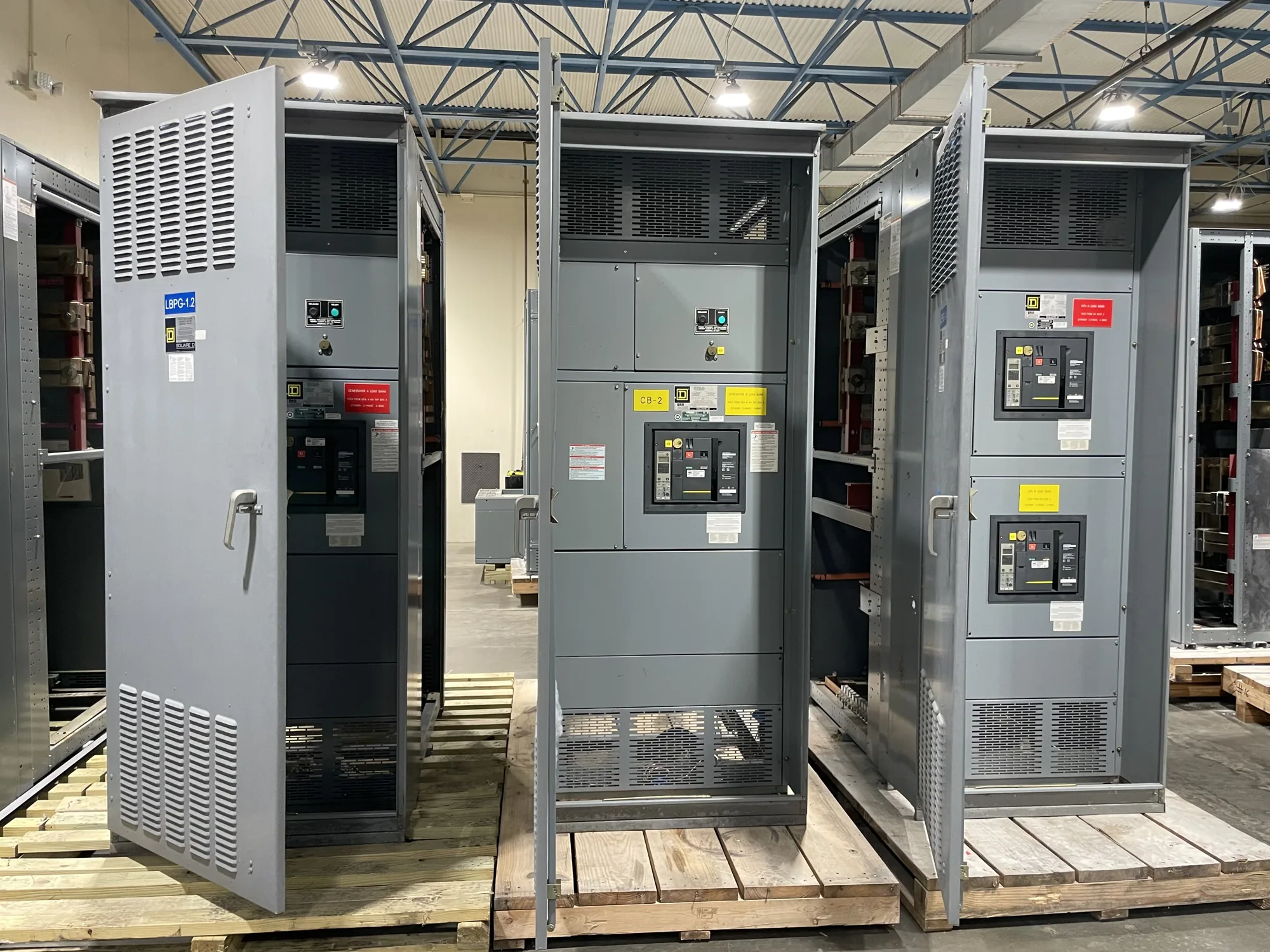
Start with the process distribution plan
Chemical processing facilities often combine continuous or batch operations, large motor-driven equipment, utilities, and support systems. Their electrical distribution must reflect how each process area is supplied and what loads need to remain available during normal operation, maintenance, or an interruption. For a new switchgear project, begin with the one-line diagram and the facility’s operating priorities rather than selecting equipment from a broad industry label.
Identify the distribution points serving process units, pumps, compressors, mixers, heating or cooling systems, and plant services. Confirm which loads start together, which may restart in sequence, and which require separate feeders or operating arrangements. The responsible electrical engineer should establish load assumptions and system configuration; equipment selection follows those project-specific inputs, not a generic chemical-plant template.
Address hazardous-area boundaries early
Some chemical processing operations may include areas classified because of flammable gases, vapors, or combustible dust. Classification depends on the materials, process conditions, and applicable project assessment. Do not assume that a whole facility—or every process building—has the same classification. The owner and qualified design professionals should define classified boundaries and communicate them on project drawings before switchgear location and room arrangements are finalized.
Switchgear placement is a coordination issue as much as an electrical one. The design team should assess whether a proposed electrical room is outside unsuitable classified areas, how cables reach process loads, and whether access, ventilation, environmental conditions, and future maintenance needs are addressed. If the location or boundary is uncertain, resolve it with the responsible engineer rather than relying on a product description to establish suitability.
Coordinate motor loads and protective functions
Motor-heavy process distribution can affect feeder sizing, starting conditions, protection, and the way upstream and downstream devices coordinate. Provide motor data, starting methods, expected operating patterns, and any process sequencing assumptions available to the project team. The engineer can use those details to evaluate the system and specify protective functions and settings. Do not assume that a standard lineup or a nominal current value alone establishes coordination.
Protective coordination should be reviewed across the relevant sources, switchgear, feeders, motor-control equipment, and downstream loads. The project may require evaluation of fault conditions, selectivity, arc-flash considerations, or continuity goals, but the applicable analyses and equipment configuration must be determined for the actual system. Share available short-circuit information, transformer data, conductor details, and existing one-line drawings so the design and equipment scope can be checked together.
Choose voltage class and distribution arrangement
Low-voltage switchgear, including equipment in the 480 V class, may serve distribution points where the project’s system and load requirements fit that class. Medium-voltage switchgear, such as 5 kV or 15 kV class equipment, may be considered for other parts of a facility distribution system. These examples describe voltage classes, not a recommendation for a particular plant. The engineer should identify the nominal system voltage and specify the equipment’s required ratings for the application.
Confirm how nominal voltage, equipment maximum voltage, insulation requirements, grounding method, and system configuration relate in the project specification. Available source capacity, transformers, feeder distances, expansion plans, and operating strategy can affect where transformation and distribution equipment belong. Do not treat nominal voltage and equipment maximum voltage as interchangeable, or infer one rating from another. Ask the project engineer to resolve these points before requesting a final equipment configuration.
Translate plant needs into an equipment specification
A useful RFQ package identifies the application, one-line diagram, voltage class, source and load data, bus and feeder requirements, protective-device preferences, enclosure and room conditions, and any project-required testing or documentation. Include the applicable drawings and revision status, delivery destination, requested schedule, and the party responsible for engineering decisions. Clearly mark information that is preliminary so assumptions can be identified before they affect the design.
Discuss whether the requested equipment is low-voltage switchgear, a low-voltage switchboard, or medium-voltage switchgear; these terms describe distinct equipment categories and should match the project scope. For eligible low-voltage switchboards, UL 891 may be relevant, but applicability and assembly listing must be verified for the specific design. Do not extend that standard to medium-voltage switchgear or assume any listing, rating, test, or compliance claim without confirmation for the supplied configuration.
Coordinate procurement, review, and delivery
Owners, engineers, contractors, and purchasing teams should agree on who will approve drawings, answer technical questions, coordinate interfaces, and receive the equipment. Confirm cable entry, access clearances, room dimensions, conduit or bus connections, lifting and handling constraints, and integration with adjacent equipment. Review submittals against the current project documents, and capture approved deviations in writing so procurement and installation teams work from the same scope.
South Carolina Switchgear Builders manufactures new switchgear and switchboards in the United States using all-American components, offers custom-to-specification equipment, and ships nationwide. Short lead times may be available, but availability and actual lead time depend on the order and must be confirmed. Provide the complete technical package and schedule needs for review; the final design, ratings, delivery date, listing, and testing requirements remain subject to the project specification and confirmation for the equipment supplied. Installation, testing, and maintenance should be performed by qualified personnel under applicable safety procedures.