Frame the project around its electrical scope
For a Greenville-area project, begin with the change the electrical distribution system must support: a new facility, an expansion, replacement of an existing assembly, or feeder work staged around continuing operations. These are planning scenarios, not assumptions about a particular site. Define the loads, service arrangement, project boundaries, and construction phases before comparing equipment options.
Separate present requirements from future provisions. A planned production line or campus building may affect the required distribution arrangement, but spare capacity should be based on the responsible engineer’s load assessment, not an informal percentage. Record which feeders and loads are in scope, what must remain operational during each phase, and where the equipment must fit.
Choose the equipment class and configuration
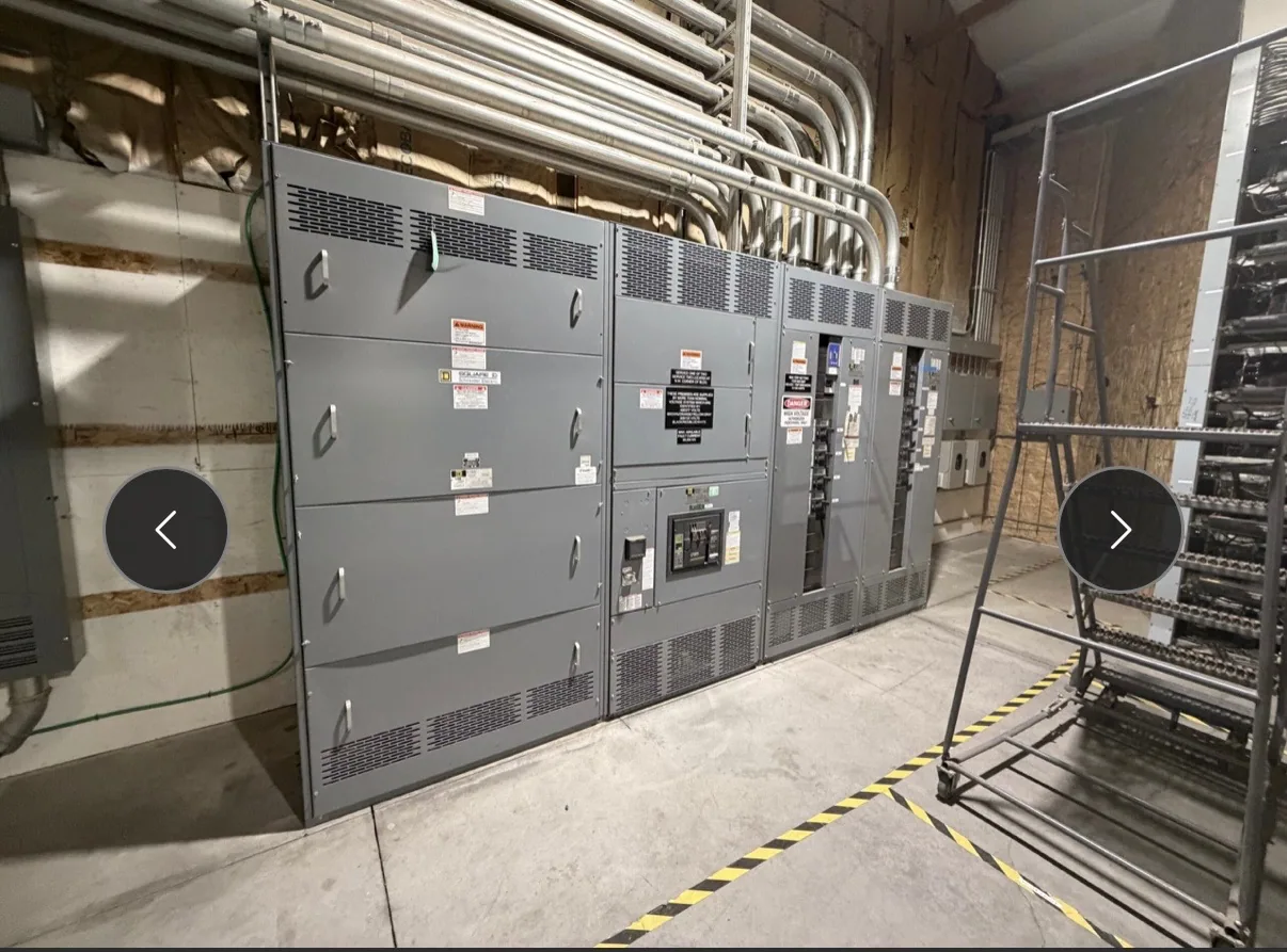
Confirm whether the project calls for low-voltage switchgear, a switchboard, or another distribution assembly. A 480 V class system is low voltage; medium-voltage equipment, such as 5 kV or 15 kV class designs, has different application and coordination considerations. The one-line diagram, system voltage, available fault information, and project specification should guide the selection rather than a product label alone.
For a low-voltage application, review the main and feeder arrangement, protective-device functions, metering needs, enclosure and access constraints, and how conductors enter and leave the assembly. A switchboard may be appropriate in some applications, but its role and construction are not interchangeable with every switchgear design. UL 891 applies only to eligible low-voltage switchboards; confirm whether it applies and whether the specific assembly is listed as required by the project.
Plan around production and access constraints
Manufacturing expansions can make outage windows, equipment access, and the order of feeder changes central design inputs. Map the proposed installation route, room clearances, doors, lifting or handling constraints, cable paths, and the space needed for qualified personnel to work under applicable safety procedures. Confirm these conditions against drawings and site measurements before finalizing dimensions or shipping arrangements.
Where operations must continue through staged work, identify which loads can be isolated in each phase and which interfaces must be ready before a transition. The equipment design itself cannot establish an acceptable outage plan. The facility team, project engineer, and electrical contractor should coordinate construction sequencing, switching responsibilities, temporary arrangements if applicable, and commissioning requirements for the specific site.
Evaluate protection and coordination as a system
Protective devices need to be considered in relation to the full distribution system, not selected independently from a catalog. The time-current behavior of upstream and downstream devices, available fault current, connected loads, and the owner’s continuity objectives all affect the analysis. Selective coordination requirements, when applicable, must be evaluated for the actual system and specification by the responsible engineer.
Provide the available one-line diagram and relevant study information when requesting a configuration. Identify existing upstream devices, downstream equipment, system grounding details, and known design constraints. If studies are incomplete, say so and ask which inputs are needed before the equipment design can be confirmed. Do not assume coordination, interrupting capability, ratings, or compliance from a general product description.
Use a hypothetical production expansion to test assumptions
Consider a hypothetical automotive manufacturing expansion that adds process loads while existing production remains in service. The buyer and engineer might compare a new low-voltage switchgear arrangement with other suitable distribution options by examining feeder count, load characteristics, room layout, maintenance access, and planned outage windows. This example does not describe a real customer, site, or installed assembly.
Ask whether the proposed sections can be transported and installed through the available route, whether cable terminations match the design, and how the new feeders connect to the existing system. Also clarify which loads require monitoring or particular protective functions. These details can change the physical layout and component selection, so resolve them in the project documents rather than relying on a generic capacity statement.
Prepare a useful request for quotation
A focused RFQ should include the project location, requested equipment class and system voltage, one-line diagram, applicable specifications, load and feeder schedule, available fault-current information, and required protective-device or metering functions. Add room drawings, cable-entry preferences, environmental conditions, access limitations, and any phased construction or outage constraints. Mark unconfirmed data clearly so design assumptions can be reviewed.
State the required documentation, drawing review milestones, testing or listing requirements, delivery destination, and the date by which equipment is needed on site. Availability and actual lead times depend on the order and must be confirmed; do not treat a requested date as a delivery commitment. Project-specific ratings, testing, standards, and listing applicability also require confirmation against the final specification and supplied equipment.
Coordinate design, delivery, and installation
South Carolina Switchgear Builders manufactures new switchgear and switchboards, with US-built equipment, all-American components, custom-to-specification options, and nationwide shipping. For a Greenville project, confirm the service-area fit, equipment configuration, availability, and delivery schedule directly for the order. These general capabilities do not establish a particular design, rating, listing, or lead time.
Before release, align approved drawings with the project engineer, contractor, and facility stakeholders; confirm responsibilities for site preparation, receiving, installation, and required verification. Installation, testing, and maintenance should be performed by qualified personnel following applicable safety procedures. With scope, engineering inputs, access conditions, and project milestones documented, the buyer can seek a proposal that reflects the actual Greenville-area project rather than a generic equipment assumption.