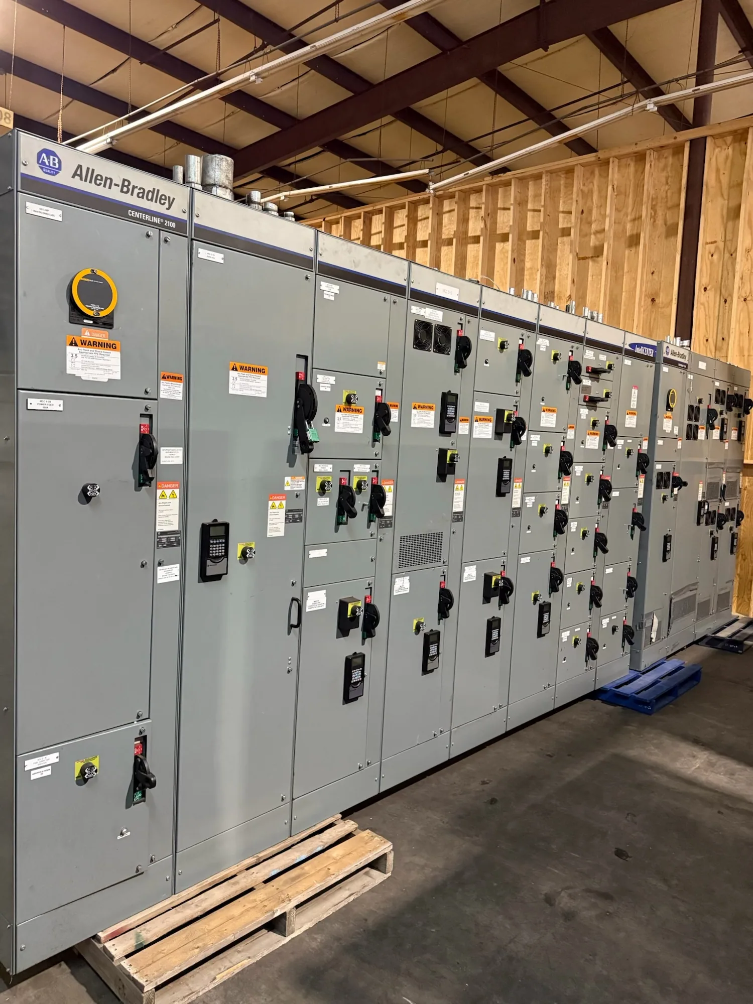
Define the facility scope and process boundaries
Industrial switchgear must fit the electrical system and the process it serves. A facility may have large motors, production lines, building services, utility interfaces and essential process loads, each with different consequences if power is interrupted. Start by identifying the equipment included in the project and the points where existing distribution, new gear and downstream systems connect.
Clarify whether the work is a replacement, an expansion or a new installation. Record which loads must remain operating, which can be shut down, and whether temporary operating arrangements are feasible. These boundaries help the project team compare equipment arrangements and plan installation without assuming that every load can be transferred or every outage can be scheduled the same way.
Match the equipment to loads and voltage class
Provide the responsible engineer’s one-line diagram, nominal system voltage, phase and frequency, incoming source details, and the load schedule. Identify motors by their relevant nameplate and starting information, along with major variable-frequency drives, transformers, capacitors and other loads that can affect system behavior. The engineer can then establish the applicable equipment type and ratings from the actual system requirements.
Industrial projects may call for low-voltage switchboards, medium-voltage switchgear, or distinct equipment at different points in the distribution system. A 480 V class application is low voltage; 5 kV and 15 kV class applications are medium voltage. Do not select equipment based on a general label alone. Confirm voltage class and all required ratings against the study, system conditions and project specification.
Coordinate motor starting and protection
Motor starting can influence voltage drop, source loading and protective-device selection. Share starting methods, motor duty, expected operating sequences and any known limits on starts or simultaneous operation. The project engineer should evaluate those conditions with the available source information and load behavior. A lineup that serves a steady load may need different consideration when large motors start or production loads change rapidly.
Protection should be considered across the complete path from source through switchgear to downstream equipment. Provide available fault-current information and the applicable short-circuit, coordination and arc-flash study requirements, or identify who will produce the studies. Device functions, settings, interrupting capability and selective coordination are design-dependent. Confirm the intended approach with the responsible engineer rather than assuming a generic configuration will suit the facility.
Plan interfaces, access and maintainability
Document cable entry direction, conductor sizes and quantities, termination requirements, bus connections and interfaces to transformers or downstream distribution. Include room dimensions, equipment access routes, working clearances and restrictions on moving or lifting sections. These details affect lineup arrangement and connection planning; they should be reviewed before a design is finalized, especially when existing infrastructure limits where new equipment can fit.
Consider the facility environment and operating plan. Provide known ambient conditions, elevation if relevant to the specification, dust or moisture exposure, corrosive conditions, ventilation constraints and any enclosure requirements. Explain how operations expects to isolate equipment for inspection or maintenance and which process areas cannot tolerate an interruption. Qualified personnel must perform installation, testing and maintenance under applicable safety procedures; never plan work that depends on energized intervention.
Balance continuity with project constraints
For a hypothetical plant expansion, the project team might need to add feeders while keeping an adjacent process area in service. That premise does not establish that a particular tie, transfer scheme or staged installation is suitable. The engineer must verify system topology, protection, available space and operating procedures. Defining process boundaries early helps the manufacturer identify equipment interfaces and lets the project team evaluate practical outage stages.
More compartmentalization, monitoring or specialized construction may address stated operating needs, but can also affect footprint, cost, integration and delivery planning. Conversely, simplifying a lineup is useful only if the resulting arrangement satisfies the protection and operating requirements. Specify the function each requested feature must serve, then confirm design-dependent details, listing applicability, testing and ratings against the actual equipment documentation.
Prepare a complete equipment request
For a useful quotation, assemble the current one-line diagram, load schedule, equipment specification, fault and coordination study information, and known source characteristics. Include the required voltage class, ratings, number and type of incoming and feeder circuits, motor-related requirements, enclosure and environmental conditions, and interface details. Mark information that remains preliminary so assumptions can be identified rather than mistaken for approved design criteria.
Also state the project location, requested delivery window, drawing and submittal needs, outage limits, installation sequence and who is responsible for engineering studies and field connections. South Carolina Switchgear Builders manufactures new switchgear and switchboards to specification, with US-built equipment, all-American components and nationwide shipping. Availability and lead times depend on the order and must be confirmed. A complete request supports a focused review of scope, configuration and schedule before equipment is specified for the facility.