Define the coordination objective and scope
Selective coordination is a design objective for protective devices in series: when a fault occurs, the device nearest the fault should operate while upstream devices remain closed when the specified conditions permit. This can limit the area interrupted and help preserve service to unaffected loads. It is not a general property of a switchgear lineup; it depends on the complete distribution path, device selections, settings, and the range of fault conditions under review.
Start by identifying which circuits and operating modes the project includes. A coordination study may need to consider a utility source, generators, transfer equipment, transformers, feeders, and branch circuits, where present. The responsible engineer should establish applicable code and project requirements, the portions of the system that require coordination, and the fault-current range to be evaluated. Those decisions define what the equipment specification must support.
Gather the system data before selecting equipment
Useful inputs include a current one-line diagram, source and transformer information, conductor details, grounding arrangement, anticipated operating modes, and available fault-current data at relevant points. Provide load and feeder information, including motor contributions or other sources when applicable. Identify existing equipment that connects to the new distribution, because its protective devices can affect the coordination assessment even when they are outside the new lineup.
Device documentation matters as much as nominal ratings. The engineer needs the proposed protective-device types, trip-unit or relay functions, adjustable settings and applicable time-current curves. Confirm which data are preliminary and which represent the intended supplied configuration. If exact device selections are not yet settled, document assumptions and request review of the resulting coordination limits before procurement. Missing or inconsistent inputs should be resolved, not silently replaced with assumed values.
Evaluate response across the specified range
Time-current curves help compare how devices respond to overcurrent. The engineer checks whether downstream protection operates before upstream protection over the project’s defined range, accounting for device tolerances and the characteristics of the actual components. A visible gap between plotted curves alone does not prove coordination under every condition. The assessment also needs to account for instantaneous response, short-time behavior, ground-fault functions where applicable, and manufacturer data for the selected devices.
Results may differ between normal and alternate source configurations. A generator or a transfer to another source can change available fault current, while transformer impedance and feeder length influence conditions at downstream devices. Specify the modes to be evaluated and ask the design team to explain any areas where coordination is limited. Do not treat a single assumed fault-current value as representative of every operating condition in a multi-source system.
Balance continuity with protective performance
Coordination is not achieved by delaying every upstream device without limit. Settings and device choices also need to meet the project’s requirements for interrupting capability, equipment protection, and the intended operating scheme. Longer clearing times can introduce other design concerns; the responsible engineer should assess those alongside the continuity objective. The acceptable balance depends on the system, applicable requirements, and the consequences of interruption, rather than a universal setting or rating.
Consider a conceptual path from medium-voltage protection through a transformer to low-voltage switchgear and downstream feeders. The engineer must assess the devices on both sides of the transformer using appropriate system data and manufacturer characteristics; a curve comparison cannot assume identical voltage classes or interchangeable device behavior. If a feeder fault is meant to be isolated locally, verify the upstream response for the relevant fault range and operating modes. Confirm any exceptions explicitly.
Specify equipment in the context of the study
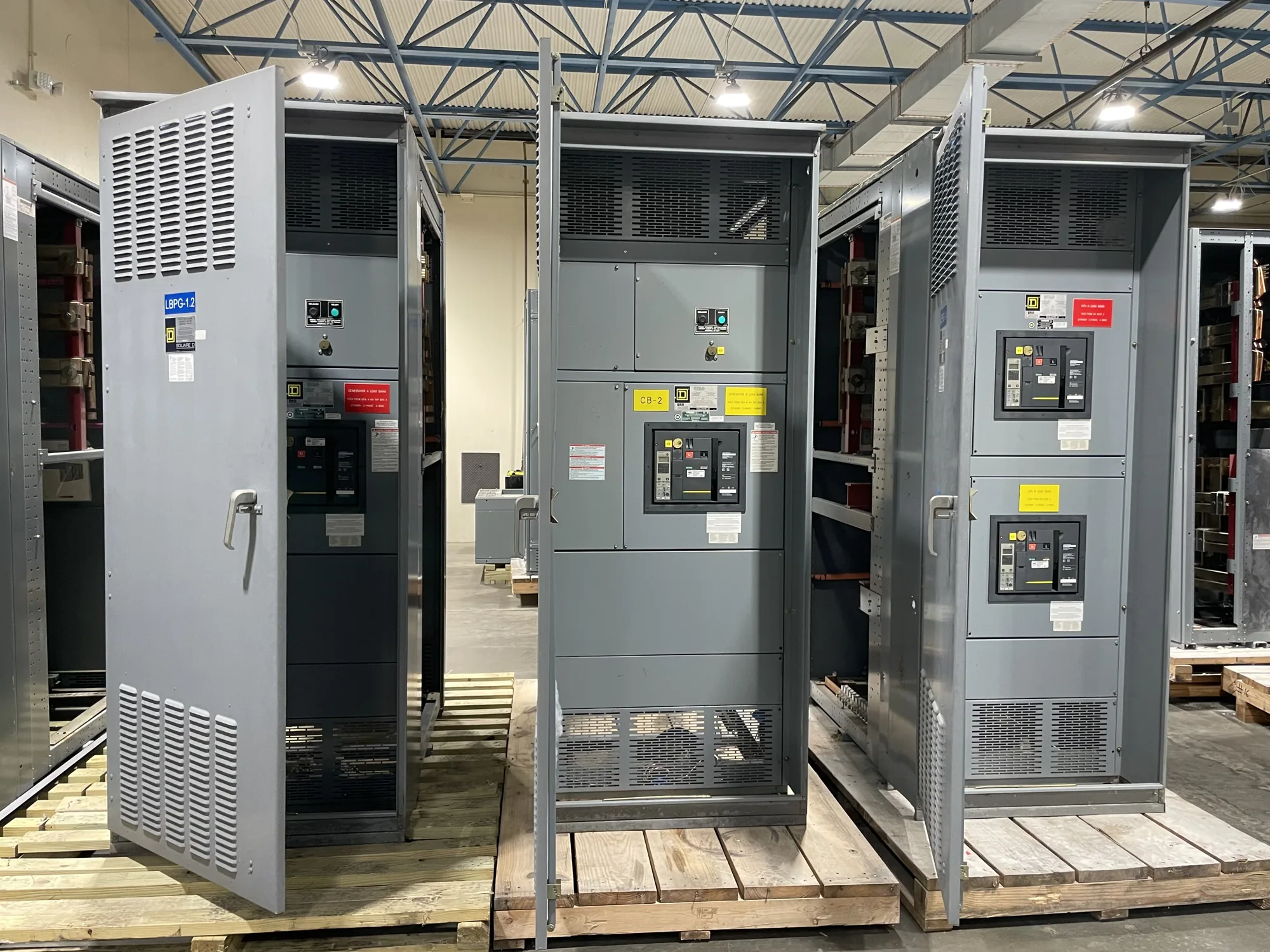
For new switchgear or switchboards, provide the equipment manufacturer with the approved one-line, project specifications, device requirements, and coordination-study assumptions. State voltage class, system arrangement, source options, required protective functions, and known interfaces. Identify whether the design is for low-voltage switchgear, medium-voltage switchgear, or a switchboard; these are not interchangeable terms. Any proposed configuration, device availability, ratings, listing, or standards applicability must be verified for the actual design and supplied equipment.
South Carolina Switchgear Builders manufactures new equipment to specification, with US-built equipment and all-American components; nationwide shipping is available. Configuration and lead time depend on the order and must be confirmed. Ask how the proposed equipment data will be documented for the engineer’s review, and coordinate changes to protective-device selections or settings before the approved design is released. Equipment procurement supports the study; it does not replace engineering analysis.
Use a practical review checklist
Before requesting a quotation or finalizing a specification, assemble the system one-line, available source and fault-current information, operating modes, connected load details, and the required coordination scope. Include the governing project requirements, proposed device functions and settings where known, and the documentation needed for evaluation. Ask the responsible engineer to identify assumptions, study boundaries, exceptions, and the conditions that would require a design revision.
Also confirm who will provide final device data, review the study against the equipment submittal, and resolve discrepancies before installation. Request the applicable drawings and manufacturer information needed for that review. Installation, testing, and maintenance should be performed by qualified personnel following applicable safety procedures. A clear specification gives the design team and manufacturer a common basis for selecting new equipment while preserving the engineer’s responsibility to verify protection for the completed system.