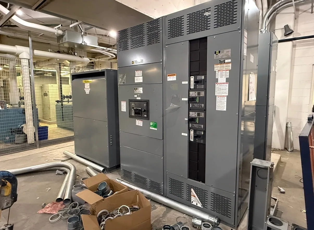
What a motor control center does
A motor control center (MCC) groups motor branch-circuit and control equipment in a coordinated assembly. Depending on the design, sections may contain motor starters, variable-frequency drives, feeder devices, control components, and associated wiring. The selected configuration must match the project’s motor loads and electrical system; an MCC is not simply another name for switchgear.
For a South Carolina facility planning new equipment, the key question is whether a grouped MCC arrangement suits the loads, operating practices, and space available. A switchboard or other distribution equipment may serve different functions, such as distributing power to downstream circuits. The project engineer should establish the system architecture and identify where the MCC fits before equipment is specified.
Match motor controls to the application
List each motor’s application, electrical characteristics, starting requirements, operating pattern, and control needs. The engineer can then determine whether a starter, drive, or another arrangement is appropriate for each load. A drive may be considered where adjustable speed or process control is required, while a starter may suit a motor intended to operate at a fixed speed. The equipment schedule should make those distinctions clear.
Also identify feeder protection, disconnecting means, control power, interlocks, communications, and any required separation or enclosure features. These are design questions, not universal package assumptions. A custom assembly should reflect the project specification, including which components are supplied in the MCC and which are furnished or connected elsewhere.
Verify voltage, current, and system details
Provide the nominal system voltage, phase and frequency, grounding arrangement, and available system information established by the responsible electrical designer. Confirm the equipment’s voltage class and maximum-voltage requirements against the system; nominal voltage alone does not establish suitability. Insulation and component selection also depend on the specified system configuration and the actual assembly design.
For each motor and feeder, provide normal load current and relevant device requirements. Bus and device current ratings must suit the defined loads and operating conditions. The project team should account for applicable ambient temperature, enclosure conditions, grouping, ventilation, and any required derating. Heat from drives and other components can affect arrangement and thermal design, so identify expected operating conditions rather than assuming a standard configuration will fit.
Plan for production needs and future loads
Consider a production line with several motors, such as conveyors, pumps, and process equipment. The useful design question is not only how many motors operate today, but which must start together, which run continuously, and whether speed or sequencing control is needed. Those details influence device selection, control interfaces, operating strategy, and the way loads are grouped into sections.
Discuss planned expansion early. Spare physical space, provisions for future units, and capacity in the electrical design are separate considerations; one does not guarantee the others. The engineer should define the expected additions and evaluate their effect on bus loading, feeder protection, heat, and available space. This helps the buyer compare a compact present-day arrangement with a design that better accommodates a documented growth plan.
Coordinate the assembly with the facility
Provide layout constraints, access requirements, environmental conditions, cable entry preferences, and the intended installation location. Confirm dimensions and routing with the facility team before finalizing the arrangement. The electrical contractor should coordinate the installation plan, terminations, and connection to upstream and downstream equipment with the design documents and site conditions.
Establish responsibility for controls integration, communications, field wiring, and startup documentation. The owner, engineer, contractor, and equipment manufacturer may each have different scopes. Clarifying interfaces before release helps prevent gaps, such as an assumed control signal or field connection that is not included in the equipment supply. Installation, testing, and maintenance must be performed by qualified personnel following applicable safety procedures.
Prepare a useful RFQ
A project inquiry is more productive when it includes the one-line diagram, motor schedule, system voltage and configuration, load data, control narrative, protection requirements, and any defined environmental or layout constraints. Note the required section arrangement, incoming and outgoing connections, future provisions, and project milestones. Identify applicable project specifications and requested documentation so the proposed configuration can be reviewed against the actual design.
- List motor loads, starter or drive preferences, and operating requirements.
- State system voltage, phase, frequency, grounding, and available fault information as confirmed by the engineer.
- Describe bus and device requirements, enclosure conditions, heat considerations, and installation constraints.
- Identify control interfaces, communications, future loads, and scope boundaries.
- Request confirmation of the proposed ratings, options, listing applicability, testing, availability, and delivery schedule for the specific assembly.
Review the proposal before release
South Carolina Switchgear Builders manufactures new equipment in the United States using all-American components and can build to specification, with nationwide shipping. Configuration, availability, and lead time depend on the order and should be confirmed for the project. Review the proposal against the engineer’s requirements, especially voltage, current ratings, device selection, heat conditions, interfaces, and physical arrangement.
Before approving production, resolve open technical questions among the owner, engineer, contractor, and manufacturer, and confirm the final submittal reflects the agreed scope. Project-specific ratings, standards, testing, and any applicable listing must be verified for the actual design. A complete, coordinated specification gives the team a sound basis for comparing options and moving a new MCC from planning into procurement.