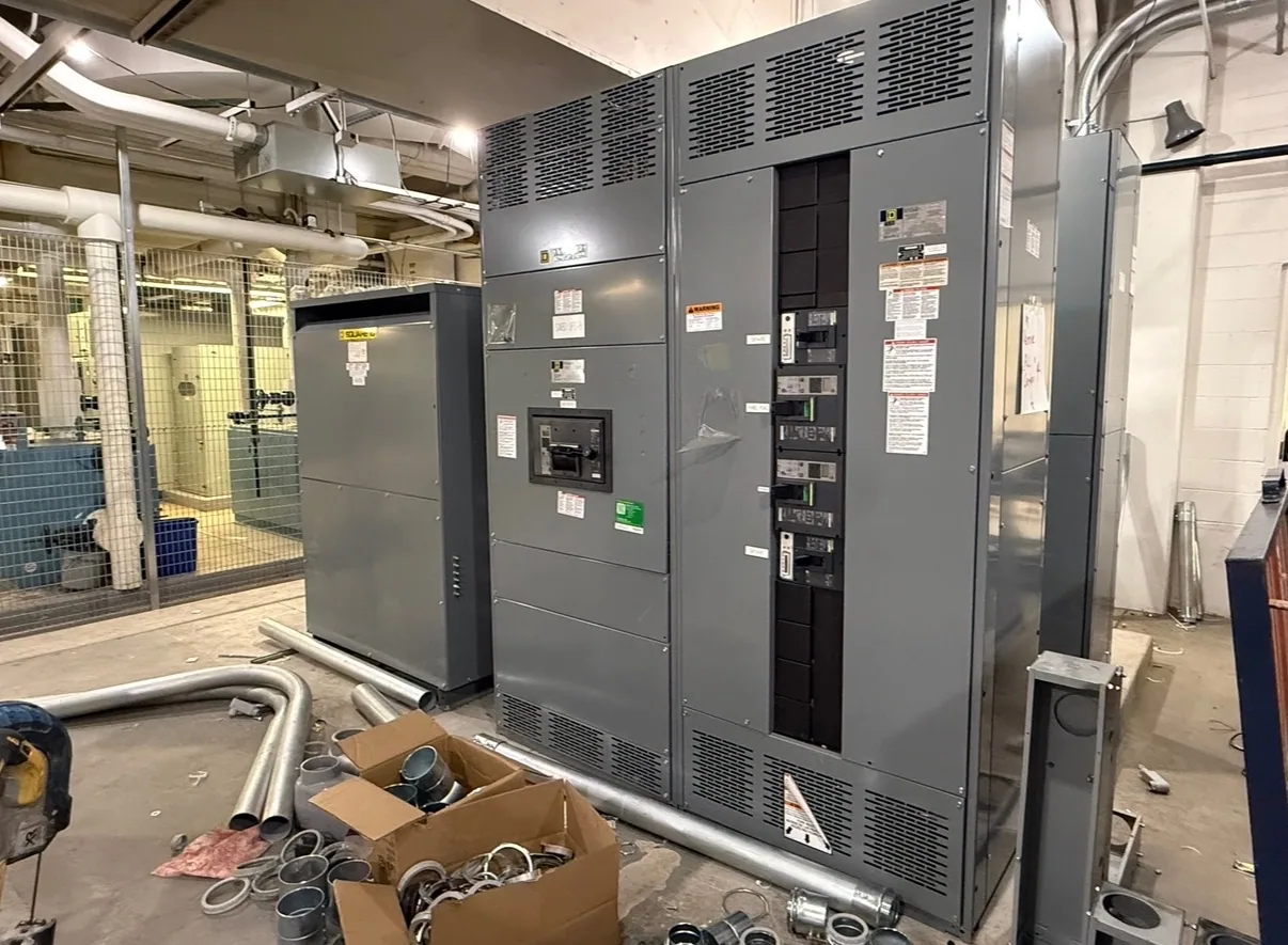
Where switchboards fit in a data center
In a data center project, a low-voltage switchboard may distribute power from a service or upstream source to downstream feeders serving areas such as IT loads, cooling equipment, and other facility systems. Its role depends on the one-line diagram and the overall distribution architecture. A switchboard is one part of that design, not a substitute for decisions about redundancy, backup generation, transfer equipment, or downstream power systems.
High-density IT loads can make capacity planning and heat removal closely connected. Cooling equipment may have different operating patterns and feeder needs from IT loads, while backup sources introduce additional operating modes and interfaces. Buyers should share the intended load categories and source arrangement with the project engineer and manufacturer. The equipment configuration must follow the actual design rather than assumptions based on the building’s use.
Match service and feeder devices to the design
Service and feeder device selection should reflect the specified system, connected loads, and protective coordination approach. Provide the responsible engineer’s device schedule or one-line diagram, including required device types and ratings. The manufacturer can use those documents to assess the requested assembly scope; the engineer remains responsible for system design and coordination. Do not choose devices solely from an estimated future load or a generic data center template.
Fault-current requirements also need project-specific review. The available fault current and required equipment ratings must be established for the actual installation and verified against the proposed design. Buyers should identify the information source and any required documentation, rather than presume a rating from voltage or application alone. Protective-device coordination with upstream sources and downstream equipment is an engineering matter that must be resolved for the particular system.
Plan for redundancy, sources, and phasing
Redundancy strategies vary. A project may have multiple sources or paths, but the switchboard arrangement must be defined by the project’s operating plan and drawings. Clarify which sources connect to the assembly, how transfers or interlocks are addressed elsewhere in the system, and what operating states the design must accommodate. Confirm responsibilities for any associated transfer equipment; do not assume it is included in a switchboard scope.
Capacity phasing can affect the initial configuration, reserved space, feeder provisions, and future expansion approach. Specify what is needed at initial delivery and what future work is anticipated, then ask the engineer to define which provisions are appropriate. Space or provisions for later additions should not be assumed to guarantee that an expansion will fit or be feasible. The final design must account for electrical requirements, physical limits, and the planned installation sequence.
Resolve voltage and equipment ratings explicitly
State the nominal system voltage and system configuration, and distinguish these from the equipment’s specified maximum voltage and insulation requirements. These terms are related but not interchangeable. Provide the project documents that establish them, and ask the responsible engineer to confirm the requirements for the actual system. Do not infer a switchboard’s ratings from a facility description or from a voltage label without checking the complete specification.
For a low-voltage switchboard, applicable listing and assembly details must be confirmed against the specific design; UL 891 applies only to eligible low-voltage switchboards, and not every assembly should be presumed listed. Fault ratings, device ratings, environmental conditions, and other requirements likewise need confirmation. Manufacturer availability, configuration, and delivery timing depend on the order and must be reviewed against the supplied specification.
Make monitoring and maintainability project-specific
Monitoring needs may include particular instruments, metering points, communications interfaces, or alarm information, but the required scope depends on the facility controls and operating plan. List what data the project expects from the switchboard and identify who supplies, configures, and integrates each interface. Verify compatibility and responsibilities with the relevant design and controls teams instead of assuming a monitoring feature is included as standard.
Maintainability begins with the room and access conditions as well as the equipment arrangement. Provide available footprint, access routes, working clearances established by the project team, cable entry preferences, and any installation constraints. Discuss how the assembly will be positioned and connected, and what access is needed for qualified personnel to inspect or service it. Manufacturer scope and field installation, testing, and maintenance are separate responsibilities unless expressly defined otherwise.
Prepare a data center switchboard RFQ
A useful request for quotation includes the current one-line diagram, load or feeder schedule, nominal voltage and configuration, source information, required fault ratings, device schedule, and any defined listing or documentation requirements. Add enclosure and environmental requirements, dimensions or room constraints, cable entry details, monitoring interfaces, and the intended phasing plan. Identify open engineering questions clearly so they can be resolved before a configuration is finalized.
Also state the project schedule, delivery destination, requested submittal information, and coordination contacts. South Carolina Switchgear Builders manufactures new switchboards to specification, with US-built equipment, all-American components, and nationwide shipping; availability and actual lead times must be confirmed for the order. The manufacturer supplies the agreed equipment scope, while project engineering, installation, and field services should be assigned and confirmed separately. A complete RFQ gives the team a sound basis to review fit, interfaces, and schedule without relying on assumptions.