Plan around production processes
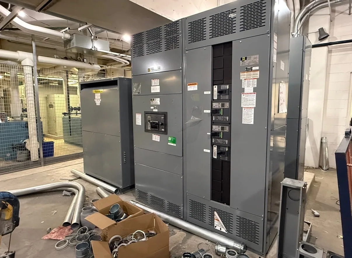
Automotive facilities bring together equipment with very different operating patterns: conveyors, pumps, fans, material-handling systems, and production machinery may all depend on motors, while line layouts and process requirements can change over time. A motor control center (MCC) groups motor branch circuits and associated controls in an assembly. It is not simply another name for switchgear, and it should be scoped around the loads and control functions it will serve.
For a hypothetical line expansion, begin by identifying which motors are new, which existing circuits are affected, and how the proposed MCC connects to the facility’s electrical distribution. The responsible engineer should confirm the system voltage, available fault current, grounding arrangement, upstream protection, and required operating sequence. These inputs help define a suitable configuration; a general industry label alone cannot determine the equipment design.
Map starters, drives, and feeder protection
Motor starting methods and operating duties affect unit selection. A project may require across-the-line starters, reduced-voltage starting, variable frequency drives, or a mix, depending on motor data and process needs. Provide motor nameplate information, expected starting frequency, control requirements, and any specified drive details. The design team can then evaluate the appropriate branch-circuit and control arrangement against the actual specification.
Clarify how each feeder is protected and how control power, interlocks, and signals interface with production equipment. Drives and other power electronics can influence heat, wiring, and electrical coordination; applicable conditions must be assessed for the particular assembly. Identify environmental conditions such as ambient temperature, enclosure location, contamination concerns, and ventilation limitations. Do not assume that a standard lineup or device selection will suit every plant area.
Coordinate outages and feeder organization
Automotive production schedules can make installation windows and cutover sequencing important design inputs. List the circuits that must remain available, the loads that can be shut down together, and any planned stages for moving production equipment. This helps the project team consider lineup sections, feeder grouping, and connection interfaces in context. It does not replace a site-specific outage plan or qualified installation planning.
Feeder segregation can make circuit identification and maintenance access clearer, but it must align with the required layout, protection scheme, and physical space. Provide available room dimensions, cable entry preferences, routing constraints, and the location of upstream and downstream equipment. Confirm who is responsible for drawings, field measurements, terminations, controls integration, and commissioning. Manufacturer equipment supply should not be confused with engineering authority, installation, or field services unless those responsibilities are expressly included in the project scope.
Resolve current ratings and heat conditions
Separate the expected operating current from the ratings of the bus, feeder devices, and motor branch components. Share motor full-load data, duty cycles, simultaneous operating assumptions, and any known load-growth plans. The responsible engineer should establish how continuous loads are treated and verify that each proposed rating fits the system and applicable design requirements. A lineup’s headline current rating does not by itself establish the suitability of every circuit or component.
Operating temperature and enclosure conditions also matter. Explain whether the MCC will sit in a conditioned electrical room, near process heat, or in another environment that could affect equipment selection. Identify nearby heat sources and any ventilation or space constraints. The effect of ambient conditions, grouping, and installed devices on ratings must be confirmed for the specific design rather than inferred from a generic product description. Provide the project’s required ratings and ask for confirmation against the proposed configuration.
Make expansion and maintenance practical
Where future production lines or motor loads are anticipated, describe the likely expansion scope instead of requesting unspecified spare capacity. Clarify whether future needs involve additional motor circuits, different starter types, drives, or a new lineup section. Physical space, electrical capacity, protection coordination, and connection arrangements are related but distinct considerations. The project engineer should determine which provisions are appropriate and document them in the equipment requirements.
Consider how technicians will identify circuits and access equipment under the facility’s safety and maintenance procedures. Provide preferences for unit arrangement, labels, control interfaces, and documentation. Any maintenance, testing, or installation work belongs to qualified personnel following applicable safety procedures; equipment planning should support the intended work practices without implying that energized work is appropriate.
Prepare a complete purchasing scope
For a useful manufacturer quotation, assemble the one-line diagram, system voltage and fault-current information, motor schedule, starter and drive requirements, protection expectations, environmental conditions, enclosure details, and physical constraints. Include the required bus and device ratings, control and communications interfaces, preferred feeder grouping, future provisions, and project milestones. Note which items are confirmed and which remain subject to engineering review.
South Carolina Switchgear Builders manufactures new motor control centers to specification, using US-built equipment and all-American components, and ships nationwide. Availability and actual lead times depend on the order and must be confirmed. Before purchase, align the proposed scope, drawings, ratings, listing applicability, testing requirements, delivery expectations, and responsibility boundaries with the project team. A well-defined package gives the manufacturer a practical basis to confirm what can be supplied for the automotive facility’s electrical plan.