Define the transfer function first
An automatic transfer switch (ATS) monitors designated power sources and transfers a connected load between a normal source and an alternate source according to its control logic. A common application uses utility power as normal and a generator as alternate, but the actual source arrangement and operating sequence must be defined for the project. The ATS is a component in a distribution system, not a substitute for system-level engineering.
Start by identifying which loads the switch serves and what the project expects when the normal source becomes unavailable, returns, or fluctuates. Clarify whether transfer is intended after a defined source condition, whether the load should return automatically, and what alarms or status indications operators need. These decisions connect the ATS to the facility’s overall operating plan and should be coordinated with the responsible electrical engineer.
Match the equipment to sources and load
Provide the available source characteristics and the load information for the specific transfer point. Useful inputs include system voltage and frequency, phase configuration, load current or other applicable demand data, load type, and any relevant starting or inrush behavior. The equipment selection must account for the actual application rather than a general description such as “backup power.” Confirm required ratings and fault-current conditions against the project design and the proposed assembly.
Also establish the number of poles and how the system treats the neutral and grounding arrangement. Whether a switched neutral is needed depends on the grounding design, source configuration, and applicable project requirements; it should not be assumed from the presence of a generator. Have the electrical engineer confirm the intended arrangement. The same review should cover load grouping, upstream and downstream protective devices, and coordination with the distribution equipment serving the ATS.
Choose a transfer mode that fits the load
Transfer behavior is a meaningful design choice. Open-transition operation disconnects one source before connecting the other, while closed-transition operation briefly overlaps sources when the design and operating conditions permit. Neither mode is universally appropriate. The choice depends on source compatibility, utility or project constraints, load sensitivity, operating objectives, and the engineered system. Specify the intended sequence and ask the responsible engineer to verify that the sources and controls can support it.
Consider whether bypass-isolation functionality is required to support maintenance while preserving a defined load supply arrangement. This changes equipment scope and must be evaluated with the project’s operating and maintenance plan. Review control power, sensing, time delays, exerciser functions if required, alarms, remote status, and any building or generator controls interface. Identify which signals are necessary, their intended behavior, and who provides and verifies each connection.
Keep ATS, switchgear and paralleling roles distinct
An ATS selects between sources for its assigned load; it does not, by itself, mean multiple generators are paralleled or managed as a coordinated generation plant. Generator-paralleling switchgear and its controls perform different functions, such as coordinating generator sources when a project requires them to operate together. If the alternate source is a paralleled generator system, define the interface between that system and the ATS, including available-source indication, permissives, and operating sequence.
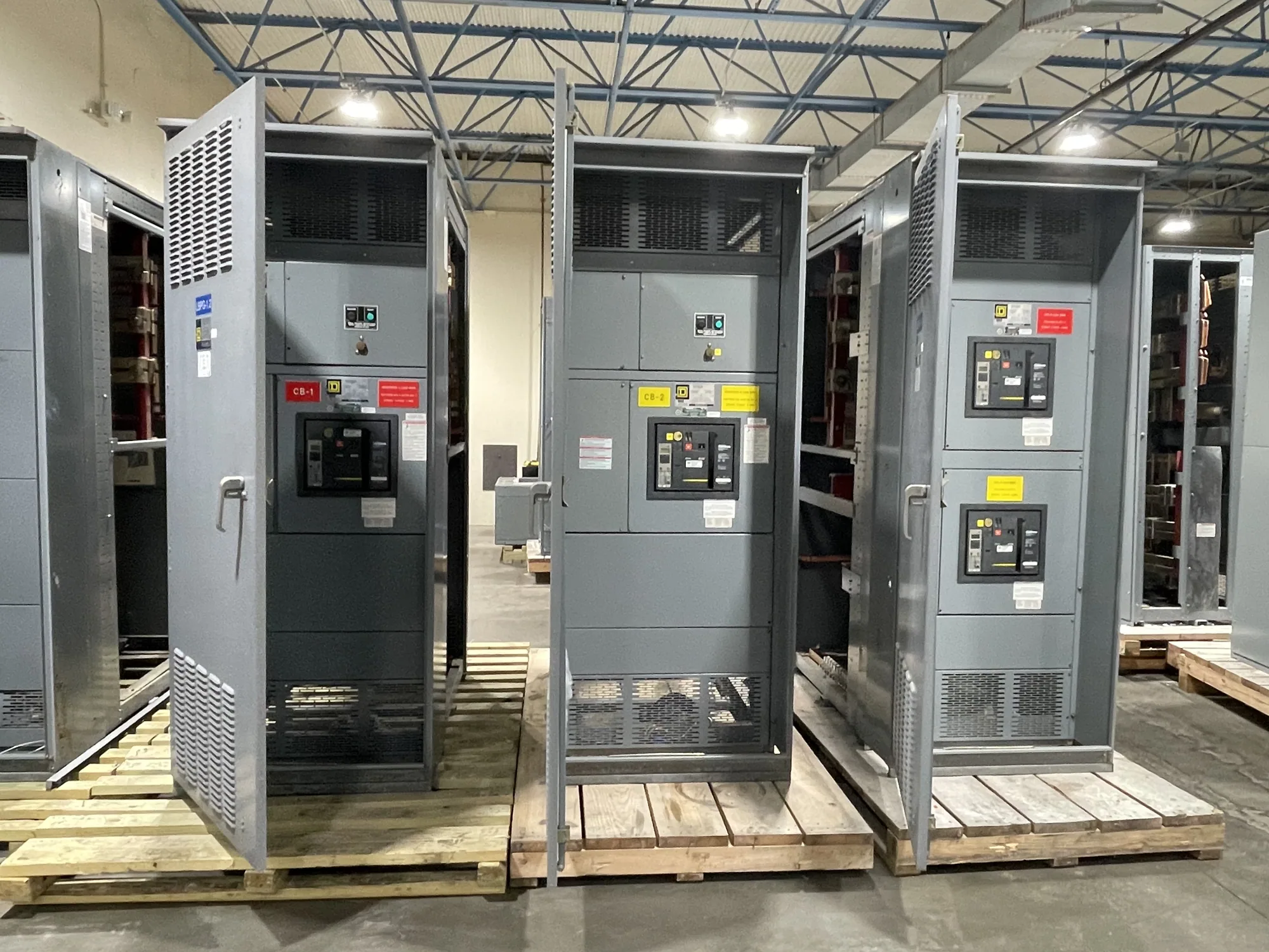
Switchgear and switchboards provide broader distribution and protection functions, with configurations determined by system design. An ATS may be supplied as part of a larger equipment package or coordinated with separate distribution equipment, but the boundaries must be explicit. Identify the source breakers, load-side protection, control wiring, and enclosure or lineup responsibilities in the project documents. Confirm which equipment is included in the purchase and which interfaces belong to other suppliers.
Review protection, coordination and compliance
Ask the project engineer to review fault-current exposure, protective-device coordination, and the ratings required at the ATS location. The switch’s suitability depends on the specified source conditions and the exact equipment configuration; a generic product label is not enough to establish application fit. Check how the ATS relates to upstream protection, downstream devices, generator protection, and any selective-coordination objectives identified for the system.
Applicable codes, standards, listing, and testing requirements should be stated for the specific project and confirmed for the proposed equipment. Do not assume that a rating, listing, or certification applies to every configuration. The purchasing specification should make required documentation and verification clear, while the responsible design professional determines the project’s code obligations and acceptance criteria.
Prepare a complete request for quotation
A useful request includes one-line diagrams, source and load data, transfer sequence, required operating mode, pole and neutral requirements, control and communications points, fault information, environmental or enclosure conditions, and any bypass-isolation expectation. Include the project schedule and identify required submittals, drawings, testing documentation, and delivery constraints. Note unresolved design questions rather than silently treating assumptions as final requirements.
South Carolina Switchgear Builders manufactures new equipment to specification, including automatic transfer switch applications, and ships nationwide. Availability and lead times depend on the requested configuration and must be confirmed for the order. Before release, coordinate the final design, interface responsibilities, submittal review, and delivery plan among the manufacturer, engineer, contractor, generator supplier, and other affected parties. Installation, testing, and commissioning should be assigned to qualified personnel following applicable safety procedures and project requirements.