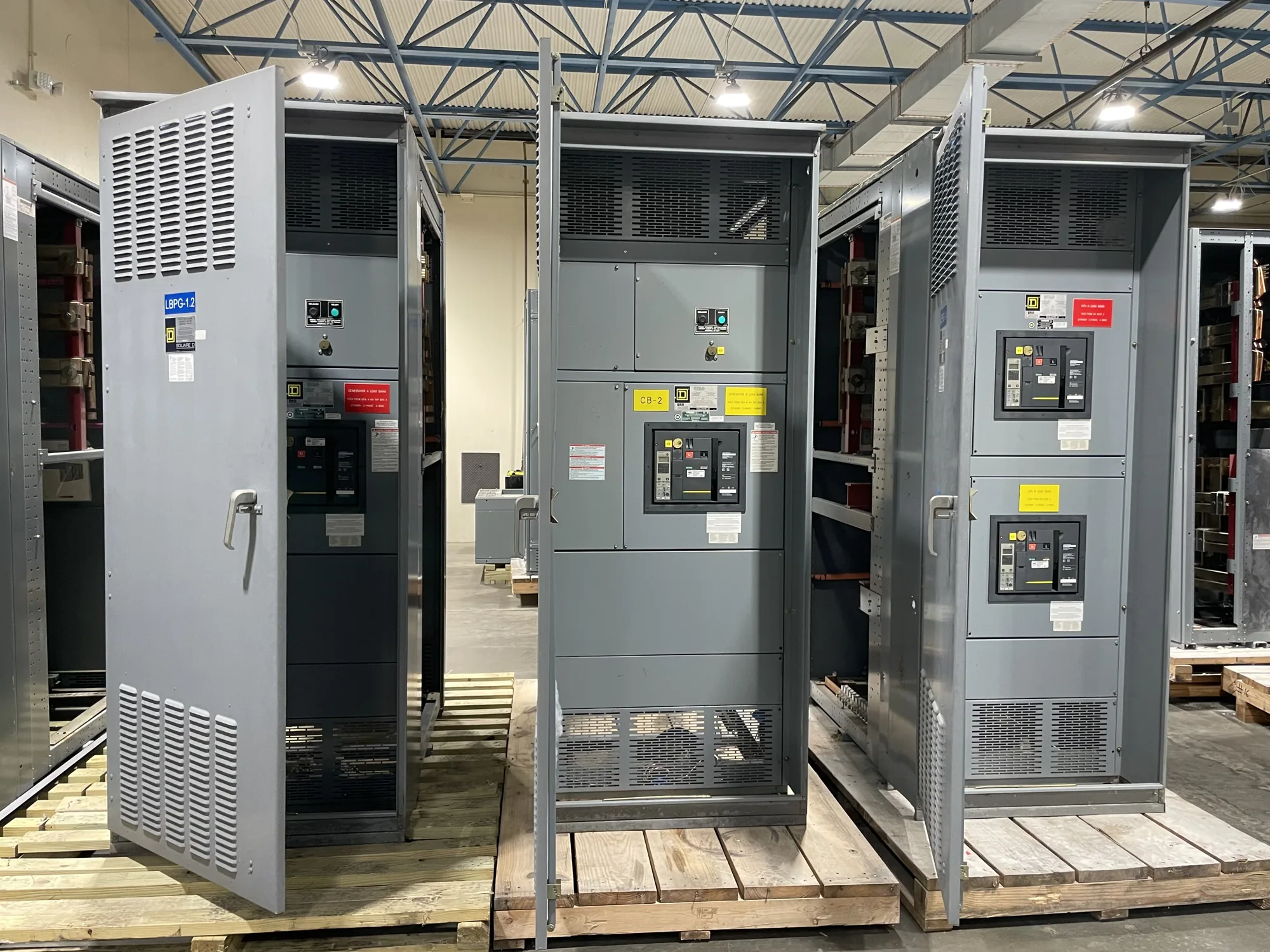
Where paralleling switchgear fits in a data center
A data center project may coordinate utility power, multiple standby generators, UPS equipment, and separate distribution paths to support critical IT loads and essential cooling. Generator paralleling switchgear can provide the equipment platform for coordinating generator sources and distributing power according to the project design. Its role depends on the one-line diagram, operating sequences, protection scheme, and interfaces with other equipment; it does not by itself establish a facility’s redundancy strategy.
Start by defining what the system must do during normal operation, a utility interruption, generator startup, and source restoration. Clarify which loads are supported, how sources are selected or combined, and what operating conditions require an alarm, transfer, or shutdown. Cooling pumps, fans, controls, and other supporting loads may have different priorities from IT loads. The project engineer should establish those priorities and the consequences of each operating state.
Translate resilience goals into operating sequences
Describe the intended source sequence in plain language before treating it as a control design. For example, identify the expected response when utility power is unavailable, when a generator fails to start, or when a running unit becomes unavailable. State whether the system is intended to parallel generators, how additional capacity is brought online, and what conditions permit reconnection to another source. The responsible engineer must determine permissible sequences and interlocks.
Synchronization, generator permissives, breaker control, protective functions, and load management need coordinated definitions. Share the generator manufacturer’s available interface information, control philosophy, and relevant operating limits for engineering review. Establish how load shedding or staged pickup should respond to available capacity, if required. Avoid relying on a generic sequence: the approved design must reflect the actual generator package, downstream equipment, facility operating goals, and applicable project requirements.
Coordinate IT, cooling, and phased capacity
High-density IT deployments can change load profiles as halls or suites are commissioned in phases. Provide present and planned load information, expected expansion stages, and any known operating scenarios that affect generator loading. Explain which loads must start together, which can be delayed, and whether cooling capacity changes with the IT load. This information helps the project team assess equipment configuration and controls interfaces without assuming future capacity is already installed.
Discuss how planned growth affects generator quantity, lineup arrangement, bus provisions, protection, and monitoring. A design intended for later expansion may involve different space, connection, and outage considerations than a single-phase installation. Confirm what must be installed initially and what future modifications are contemplated. The manufacturer can configure new equipment to specification, but system capacity, phasing, and compatibility depend on engineering review of the complete project requirements.
Resolve voltage and protection requirements
Specify the nominal system voltage and frequency, grounding arrangement, and relevant one-line details. Separately identify the equipment voltage class and the maximum voltage requirements that the responsible engineer has established. Nominal voltage alone may not communicate insulation coordination or the equipment’s required withstand characteristics. State the connection points and available fault-current information needed for equipment evaluation, and have the project engineer confirm the applicable ratings for the actual system.
Protection coordination should account for generator characteristics, connected loads, source configurations, and downstream protective devices. Provide available relay or trip-function requirements, control-power expectations, metering needs, and any required interface signals. Do not assume settings, interruption capability, or performance from a general product description. Those details must be reviewed against the project specification and supplied equipment. The voltage class and construction also determine which product category and standards may apply.
Plan controls, monitoring, and maintainability
List the signals the facility monitoring or building systems must receive, such as source status, breaker position, alarms, and measured values, when required by the project. Identify protocol, point-list, and ownership expectations early. Confirm which controls and communication functions are part of the switchgear scope and which belong to generator controls, UPS equipment, or facility systems. Clear boundaries reduce the risk of gaps between equipment packages.
Review access, lineup location, cable entry, working clearances, and planned maintenance outages with the design team. Ask how inspection or component replacement can be accommodated without conflicting with adjacent equipment or critical operating paths. Installation, testing, and maintenance should be performed by qualified personnel following applicable safety procedures. The manufacturer’s supply scope should be distinguished from site engineering, installation, commissioning, and ongoing facility operations.
Prepare a data center RFQ
A useful request for quotation includes the one-line diagram, project voltage and grounding information, generator data, sequence of operation, load priorities, fault-current and protection requirements, controls and monitoring interfaces, physical constraints, and the planned delivery phase. Include the required equipment configuration, drawings or submittals, and any project-specific testing, listing, or standards requirements for confirmation. Identify open engineering decisions instead of presenting assumptions as final requirements.
Also state the project location, schedule needs, shipment destination, and coordination milestones. South Carolina Switchgear Builders manufactures new switchgear and switchboards in the United States, uses all-American components, and ships nationwide. Configurations are custom to specification; availability and lead times depend on the order and must be confirmed. A complete RFQ gives the manufacturer and project team a clearer basis to review scope, interfaces, and delivery expectations before the equipment is specified for procurement.