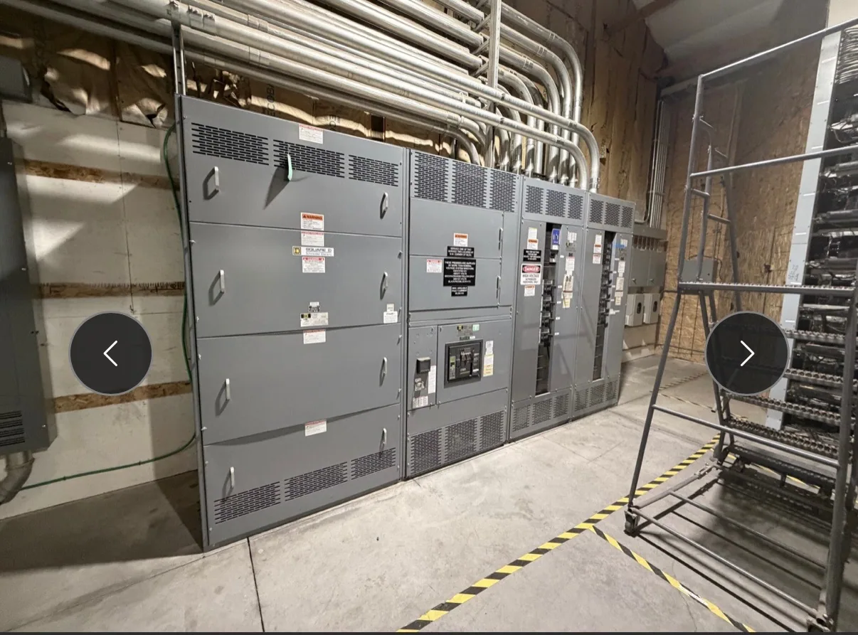
Where medium-voltage switchgear fits — Medium-Voltage Switchgear for Warehouses and Logistics Facilities
A warehouse or logistics campus may have a utility or site distribution source at medium voltage, with transformers feeding lower-voltage systems for conveyors, lighting, material handling, offices, and other loads. Medium-voltage switchgear can provide a controlled point for incoming power and feeder distribution, depending on the one-line diagram and project responsibilities. It is not a substitute for defining how each downstream system is supplied and protected.
Consider a facility adding automated sortation, more conveyor zones, or vehicle charging over several project phases. The initial design should distinguish existing loads from planned ones and identify which equipment is in the manufacturer’s supply scope. Charging demand, operating schedules, and simultaneous use are project assumptions for the responsible engineer to establish—not values to infer from the building type. That information informs feeder count, transformer planning, and potential future sections.
Set the voltage class and system boundaries
Begin with the actual system voltage and the role assigned to the lineup. Medium-voltage switchgear is distinct from a 480 V class low-voltage switchboard; the terms are not interchangeable. Confirm the nominal system voltage, grounding approach, source arrangement, frequency, and points of connection from project documents. The equipment configuration and applicable ratings must be verified against that specific system rather than selected from a generic warehouse description.
Draw clear boundaries between the switchgear, transformers, downstream distribution, and any utility-owned equipment. Identify incoming and outgoing cable connections, bus transitions, metering needs, and interfaces with other systems. If the facility will be energized in stages, show which sections serve each phase and how future connections can be made without assuming that equipment can be safely extended or worked on while energized. The responsible project team must define outage windows and safe work procedures.
Plan feeders around operations and growth
Conveyors and automated handling systems can be organized into feeder groups that reflect operating zones, maintenance priorities, or planned construction phases. Charging infrastructure may introduce a different load profile from conventional warehouse equipment. Ask the project engineer to document expected demand, diversity assumptions, operating periods, and the expansion cases that the design should accommodate. A future-load allowance should be explicit in the design basis, not an unverified promise of spare capacity.
More feeder ways can improve separation and support phased planning, but they also affect lineup arrangement, footprint, cable routing, and cost. A compact arrangement may suit site constraints but leave fewer straightforward options for later work. Discuss which feeders are required at initial turnover, which are reserved for planned phases, and whether spare spaces or future provisions are part of the requested supply. Confirm that any proposed provision fits the equipment design and project documents.
Coordinate protection, isolation, and interfaces
Protection depends on the complete power system, not just the switchgear enclosure. Provide the responsible engineer’s protective-device and relay requirements, including intended functions, control power, sensing inputs, trip interfaces, communications, and any coordination documents available for the project. The manufacturer can review the specified equipment scope and interfaces; system studies, settings decisions, and integration responsibilities should be assigned clearly among the project’s qualified parties.
Isolation and switching arrangements should match the operating concept and maintenance plan. Specify the required device arrangement, interlocks, access provisions, cable termination approach, and any separation or compartment requirements shown in the design criteria. Do not assume that a particular configuration supports a desired operating sequence until it is reviewed against the actual design. Installation, commissioning, testing, and maintenance are work for qualified personnel following applicable project and safety procedures.
Resolve continuous-current and environmental requirements
Continuous-current selection requires more than estimating a building’s average demand. The project team should provide expected normal load current for each relevant bus and feeder, planned growth assumptions, and the operating conditions used to determine required ratings. Confirm that bus, switching devices, and associated components meet the project specification together. A device rating alone does not establish that the complete lineup is suitable for the intended duty.
Review ambient and operating temperature, enclosure location, ventilation, altitude if relevant, and any conditions that could affect equipment ratings. Ask whether the project specification calls for adjustments or derating under its actual installation conditions, and have the responsible engineer resolve those requirements. Do not select a continuous-current rating solely from a transformer nameplate or a projected charging load. The final configuration, ratings, and applicability of standards require confirmation for the specific supplied design.
Prepare a useful purchase and coordination package
For a quotation, assemble the latest one-line diagram, system voltage, source and grounding details, required feeder schedule, load information, environmental conditions, and equipment location constraints. Include cable entry and termination preferences, control and relay interface requirements, metering scope, and any specified standards or project documents. Mark which loads are initial and which are future, and state whether future spaces or defined expansion provisions are requested.
Also identify required submittals, review milestones, shipping destination, and the project schedule for equipment coordination. South Carolina Switchgear Builders manufactures new equipment to specification, is US-built with all-American components, and ships nationwide. Availability and actual lead times depend on the order and must be confirmed. The manufacturer’s supply scope should be distinguished from system engineering, utility coordination, installation, field testing, commissioning, and ongoing maintenance, which must be assigned to the appropriate project parties.
A complete scope gives the manufacturer and project team a clearer basis for reviewing configuration, interfaces, and commercial requirements. Before release, reconcile the equipment proposal with the current one-line diagram, feeder schedule, protection requirements, and planned operating phases. Resolve open assumptions with the responsible engineer, especially charging demand, growth, and outage constraints. This coordination helps keep the purchased lineup aligned with the facility’s present distribution needs and its documented expansion plan.