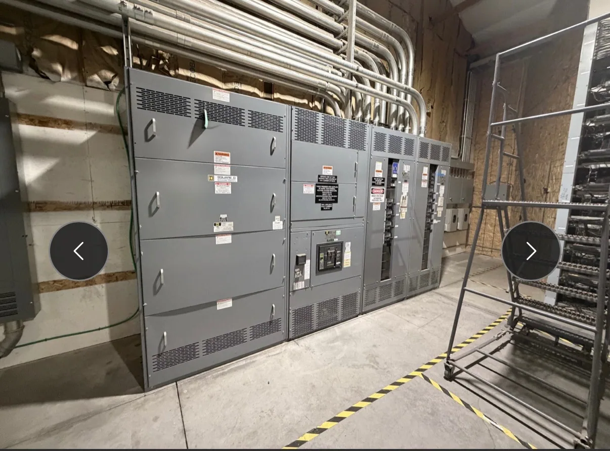
Where paralleling fits in a water or wastewater project
Consider a facility that must maintain selected pumping, treatment, and control functions when normal power is unavailable. Multiple generators can be coordinated through generator paralleling switchgear, which manages source connections and distributes power according to the project design. The arrangement may support an operating strategy in which available generation is brought online in stages rather than treating every load as equally urgent.
That strategy is site-specific. A wastewater plant may have process equipment, influent and effluent pumps, ventilation, instrumentation, and supervisory controls, while a water facility may prioritize treatment processes, distribution pumping, and monitoring. The project team must identify which loads need backup, how they are grouped, and what operating conditions matter. The switchgear manufacturer needs that defined scope to develop equipment to specification, not to decide process priorities for the owner.
Build the sequence around real operating loads
Motor starting can shape the generation and distribution design. Large pumps or other motors may create starting demands that differ from their running loads, and several starts close together may affect the system differently from one isolated start. Provide motor data, starting method, expected operating sequence, and any restrictions on simultaneous operation. The responsible engineer can use these inputs to evaluate generator capacity, source sequencing, and the proposed load steps.
Define how sources are intended to enter and leave service, which conditions permit paralleling, and what should happen if a generator does not become available. Identify priority loads and any load-shedding or restoration logic the design must accommodate. These are control and protection requirements to document and verify; they should not be assumed from the application name. Clear sequence descriptions help align switchgear, generator controls, facility controls, and the operating plan.
Coordinate synchronization, protection, and controls
Paralleling involves coordinated control of generator sources and their connection to the system. The project specification should establish the intended source arrangement, synchronization approach, metering and indication needs, protective functions, and interfaces with generator controls. Confirm which equipment or party supplies each function and signal. Interface schedules, control diagrams, and responsibility boundaries reduce ambiguity when equipment is engineered, integrated, and commissioned.
Water and wastewater sites may rely on remote alarms, plant supervisory systems, or communications between electrical and process controls. Provide required signal lists, communication protocols if specified, network boundaries, and control sequences for review. Also describe how operators are expected to view source status and respond to alarms. Manufacturer-supplied switchgear is one part of the system; generator packages, facility controls, field wiring, engineering, installation, and commissioning responsibilities must be assigned across the project team.
Resolve voltage and configuration from project documents
Start with the one-line diagram and state the system’s nominal voltage, phase and frequency, grounding arrangement, and intended source configuration. Also identify the equipment voltage class and the maximum voltage applicable to the proposed equipment. Nominal system voltage and equipment maximum voltage are related but distinct specification details; do not substitute one for the other or infer either from a facility description. Have the responsible project engineer confirm insulation and other design requirements.
Generator paralleling equipment can be specified for different voltage classes, and the correct configuration depends on the complete system design. Confirm the bus arrangement, incoming and outgoing connections, fault-current information, protective-device requirements, and any applicable project standards with the engineering team. Ratings, listing applicability, testing, and standards compliance must be verified for the actual design and supplied equipment. Provide drawings and written criteria early so questions can be resolved before the equipment scope is finalized.
Account for location, exposure, and outage constraints
Describe where the equipment will be installed: indoors or outdoors, in a dedicated electrical room or another environment, and whether exposure to moisture, corrosive agents, dust, temperature variation, or washdown is expected. Conditions vary by facility and location, so specify the actual exposure rather than relying on a general description such as “water plant.” Confirm enclosure, construction, and environmental requirements against the project conditions and applicable engineering documents.
Existing-site work may also have limited access, constrained equipment routes, shutdown windows, or requirements to keep portions of the plant operating. Share room dimensions, access and handling limits, planned outage periods, and the status of existing drawings. These constraints affect design coordination and delivery planning, but the manufacturer should not be assumed to provide field installation or outage execution. Qualified project personnel must plan and perform installation, testing, and maintenance under applicable safety procedures.
Prepare a useful purchasing and coordination package
For a quotation, assemble the one-line diagram, generator information, motor and load schedules, sequence of operation, voltage details, environmental conditions, protection and control requirements, and requested documentation. Include the project schedule, ship-to location, preferred equipment arrangement, and known interface responsibilities. Flag open engineering decisions explicitly. A complete package helps the manufacturer identify assumptions, clarify exceptions, and determine whether the proposed new equipment can be configured to the project specification.
South Carolina Switchgear Builders manufactures new switchgear and switchboards in the United States, with all-American components, custom configurations, and nationwide shipping. Short lead times may be available, but availability and actual lead times depend on the order and must be confirmed. Before releasing an order, align the approved equipment documents, scope boundaries, delivery requirements, and project schedule among the owner, engineer, generator supplier, controls integrator, and electrical contractor. That coordination gives the facility team a clearer basis for evaluating the equipment and planning the next project phase.