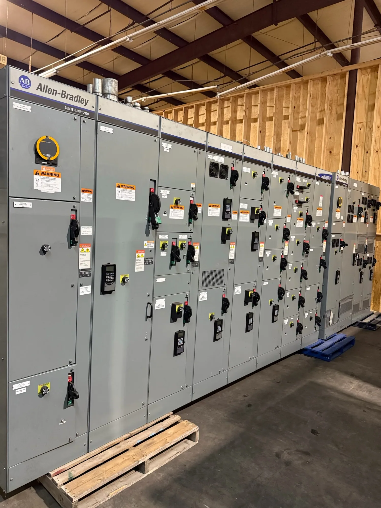
Coordinate generation across a changing campus
A commercial campus may include several buildings, separate electrical rooms, central mechanical plants, and tenants whose operating needs change over time. When standby generators are intended to operate in parallel, the paralleling switchgear coordinates their connection and operation according to a project-defined control and protection scheme. It can also form an interface to downstream distribution, but the exact boundaries depend on the one-line diagram and equipment scope.
Start by documenting which loads each generator is expected to support, how those loads reach the switchgear, and which buildings or feeders have priority. A campus plan that works for one operating phase may not fit later tenant additions or new mechanical equipment. Treat future growth as a design input to evaluate, not as capacity that can be assumed without checking the electrical design.
Define the source sequence and operating modes
Describe the intended sequence for normal utility supply, loss of source, generator starting, generator connection, load transfer, and return to normal operation. The responsible engineer should determine how synchronization is required, which conditions permit a breaker to close, and what happens if a generator or control component is unavailable. These decisions shape the control logic, protective devices, interlocks, and operator indications specified for the assembly.
For multiple buildings, identify whether generators serve a common bus, separate sections, or defined groups of feeders. Specify permitted bus ties and switching states rather than relying on assumptions about how campus sources will be connected. Changes to source configuration can affect protection coordination and operating procedures. The project team should review the proposed sequence against the campus one-line, generator data, and the intended response to credible equipment or source failures.
Set priorities for building and mechanical loads
List critical, essential, and deferrable loads in terms the design team can translate into operating logic. Elevators, life-safety systems, data equipment, pumps, chillers, and tenant loads may have different requirements; do not assume every load belongs on the same transfer step. Identify starting demands, sequencing constraints, and any loads that can be shed or restored in stages. The engineer must confirm how these priorities fit generator capability and the specified system design.
Campus loads can change as spaces are renovated or leased. Ask how future feeder additions, metering points, or tenant isolation will be accommodated, and whether spare provisions are part of the requested new assembly. Each requested provision should be shown on the drawings and included in the procurement scope. The manufacturer can build to a confirmed specification; the owner and design team remain responsible for establishing the functional requirements and approving the system architecture.
Plan feeders, metering, isolation, and phases
Provide a current one-line diagram showing generators, paralleling bus, utility connections where applicable, bus ties, feeder destinations, and existing or planned distribution equipment. Include cable or busway entry needs, physical constraints, room access, and the boundaries between manufacturer-supplied equipment and other packages. For distributed feeders, confirm how each outgoing circuit is identified, protected, monitored, and isolated for the intended operating and maintenance procedures.
Clarify what metering the project requires, where measurements must be taken, and how signals are expected to reach campus monitoring or building controls. List interface protocols or point schedules only when established by the project team, and identify the party responsible for final integration. For phased construction, show which buildings are included now, which connections are future, and what temporary operating arrangements the contractor will manage. Confirm outage windows and tie-in responsibilities with the project team; do not presume they are included in equipment supply.
Resolve continuous-current and installation conditions
Continuous-current selection should follow the actual load and system design, not generator nameplate totals alone. Provide expected normal and emergency loading, bus configuration, feeder schedules, and the duties of each switching device. The responsible engineer should confirm bus and device ratings, fault-current requirements, protective settings, and any applicable temperature or enclosure conditions. Ask how anticipated load growth is reflected, while distinguishing a specified rating from an unverified future allowance.
Operating temperature, ventilation, enclosure arrangement, conductor termination, and site conditions may affect equipment selection or usable capacity. Supply the manufacturer with available environmental and installation details so the proposed configuration can be checked against the specification. Do not infer a rating or derating factor from a general description. The final design, applicable standards, ratings, and any assembly listing must be confirmed for the specific equipment and project documents.
Prepare a focused new-equipment RFQ
A useful request for quotation includes the one-line diagram, generator information, operating sequence, load-priority schedule, feeder list, metering and controls requirements, and requested ratings. Add enclosure and room constraints, cable-entry preferences, construction phases, required submittals, and any project-specific testing or documentation requirements for review. Mark unresolved items as open questions so the manufacturer and design team can identify what needs clarification before the configuration is finalized.
South Carolina Switchgear Builders manufactures new equipment to specification, including generator paralleling switchgear, and ships nationwide. Availability and actual lead times depend on the order and must be confirmed. Equipment manufacture and supply do not replace the engineer’s system design or the contractor’s installation and field coordination. Qualified personnel must perform installation, testing, and maintenance under applicable safety procedures. With a coordinated scope and confirmed interfaces, campus stakeholders can evaluate equipment against real operating needs and plan procurement around the project’s approved design.