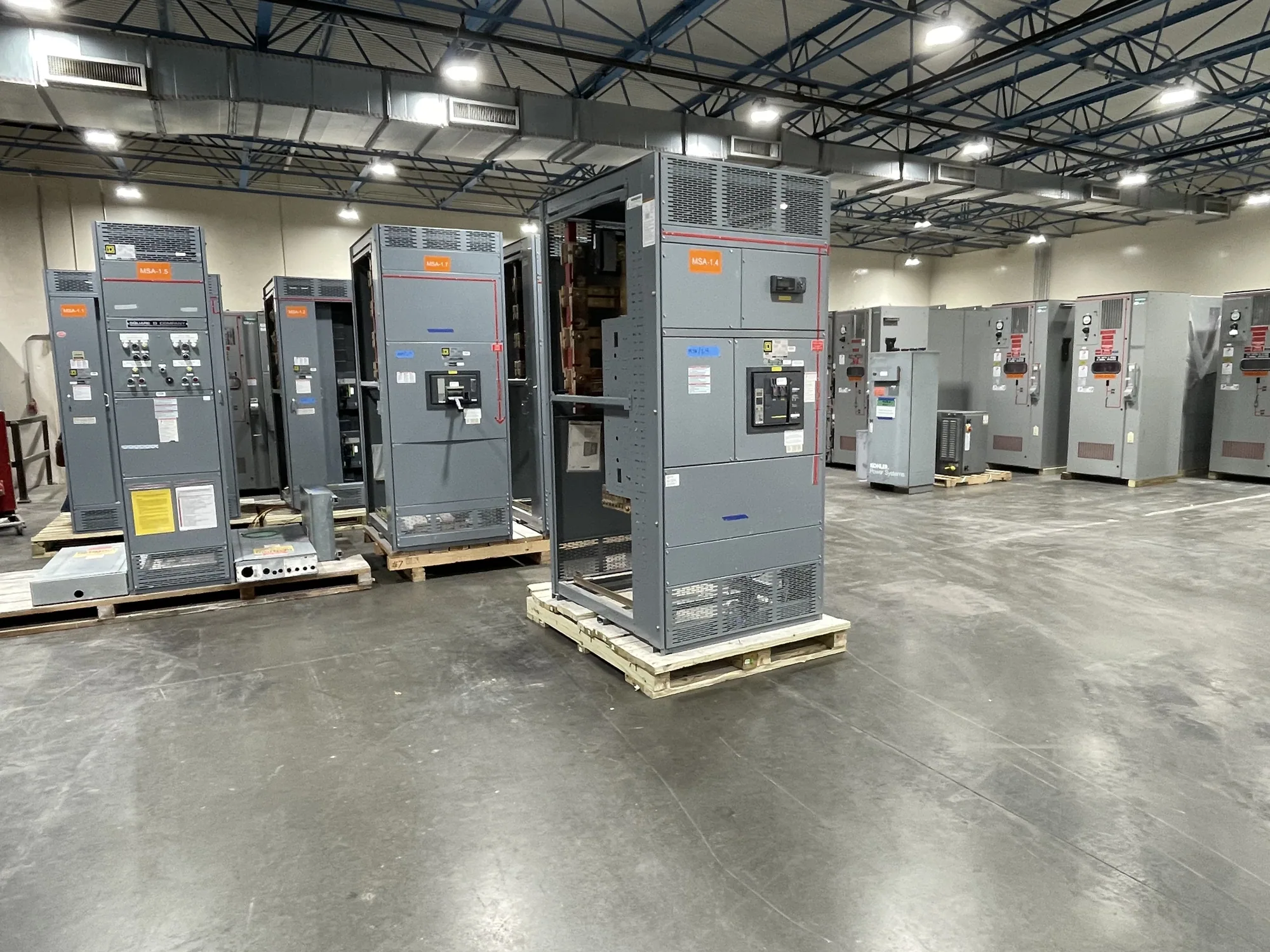
Define the design stage and its boundaries
Switchgear design engineering translates project requirements into equipment documents that the owner, engineer, manufacturer, and installation team can review. Typical starting references include the electrical one-line diagram, equipment layout, load information, and protection interfaces. The goal is not simply to draw an enclosure: the design must communicate how the specified equipment fits the electrical system and how project decisions will be verified.
Clarify who owns each decision before drawings advance. The project engineer or owner’s representative establishes system requirements and approves design intent; the manufacturer develops equipment-specific documentation within the agreed scope. Contractors, consultants, utility representatives, and component suppliers may provide information or perform separate work. Boundaries matter: a manufacturer’s equipment drawings do not automatically replace site engineering, utility approvals, installation planning, or protection-system studies.
Start with the electrical system and voltage basis
Provide the latest one-line and identify the nominal system voltage, phase and wire arrangement, grounding method, and source configuration where known. The responsible engineer should confirm the equipment’s required voltage class and maximum-voltage basis against the system and applicable project requirements. Do not treat nominal voltage alone as a complete selection rule; insulation coordination and other design conditions can affect the appropriate specification.
For medium-voltage applications, clarify the system configuration, incoming and outgoing circuits, switching functions, and interfaces with protection and control. For a 480 V-class project, describe the low-voltage distribution arrangement and connected equipment needs. These are different voltage classes and should not be collapsed into a single generic design. The engineer must establish applicable ratings and requirements for the particular project; they should not be inferred from an incomplete one-line or a broad equipment label.
Translate requirements into an equipment arrangement
Design development connects the electrical scope to physical constraints. Share room plans, access routes, equipment location, cable entry preferences, and known interface dimensions. Identify whether the design must coordinate with adjacent distribution equipment or existing site infrastructure. These inputs help reviewers consider lineup arrangement, compartment organization, access, and connection points. Final dimensions and construction details remain dependent on the approved specification and actual design.
There are practical trade-offs to resolve early. A compact layout may require closer coordination of cable access and maintenance clearances; a preferred cable-entry direction may affect the arrangement. Future provisions, spare spaces, metering, control components, and auxiliary power should be stated as requirements rather than assumed. For enclosure construction, clarify environmental exposure and project-specific enclosure needs so they can be evaluated with the fabrication scope. The manufacturer’s enclosure-fabrication work should be distinguished from site foundations, room construction, and field installation.
Coordinate protection, control, and interfaces
Protection and control requirements shape equipment interfaces, but the equipment manufacturer should not be presumed to determine the entire protection scheme. Provide the project’s protection philosophy, available relay or control requirements, interlocking intent, metering needs, and interface responsibilities. The project engineer should identify which settings, studies, control wiring, and external devices are supplied by others, and which items are included in the equipment scope.
Review circuit names, source and load designations, terminal interfaces, and control-power assumptions against the current project documents. When supplier components or contractor-provided systems connect to the lineup, define required information, responsible party, and review timing. Missing interface details can create drawing revisions or procurement conflicts. Confirm that each party is working from the same document revision, and record unresolved questions rather than treating assumptions as approved design decisions.
Review submittals as a coordinated package
Review drawings against the specification and one-line, not in isolation. Check equipment function, circuit sequence, key ratings, arrangement, connection locations, control interfaces, and stated exclusions. Confirm that design-dependent listing, testing, and standards requirements are explicitly identified for the actual assembly; applicability must be verified for the particular design. UL 891 applies to eligible low-voltage switchboards, not medium-voltage switchgear, and any assembly listing must be confirmed for the specific configuration.
Use a controlled comment process: assign reviewers, consolidate comments, identify required changes, and distinguish approval from information-only notes. Resolve conflicts between specifications, drawings, and schedules with the responsible engineer before release. Submittals are a coordination tool, not a substitute for field verification or a complete construction package. For buyers preparing a submittal package, provide clear review responsibilities and return comments within the project’s agreed schedule.
Prepare a useful design handoff
Before requesting a proposal or beginning design coordination, assemble the latest one-line, equipment specification, load and circuit schedules, room or layout drawings, protection and control requirements, and relevant interface documents. Note the project phase, required review milestones, known open decisions, and the people authorized to approve changes. If information is preliminary, label it clearly and identify when a confirmed revision is expected.
Also state the requested equipment scope, including whether the project calls for switchgear, a low-voltage switchboard, or both, and identify the intended voltage class without guessing at unprovided ratings. Ask which drawings and technical documents are included, what information remains the engineer’s responsibility, and how supplier or contractor interfaces will be handled. Clear inputs support a reviewable design and a more orderly handoff into manufacturing, fabrication, and project delivery.