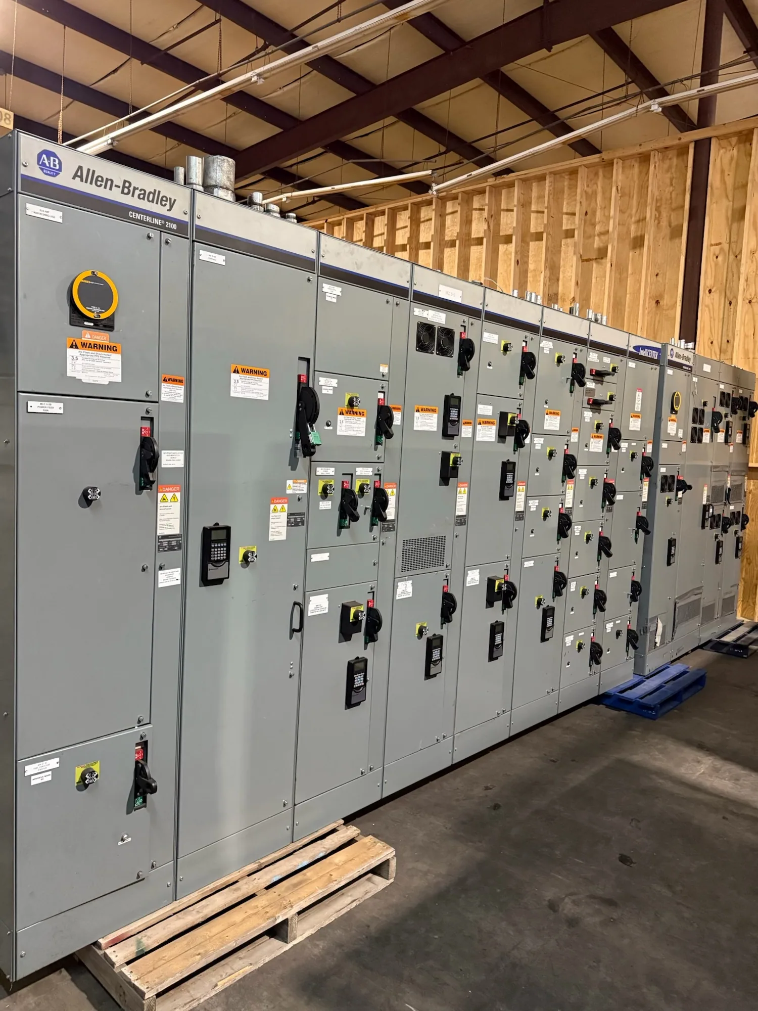
Start with the monitoring purpose
Switchgear monitoring should connect to a building management system (BMS) through an interface designed around the information the facility needs, the equipment can provide, and the project’s controls architecture. There is no single connection method suitable for every installation. First decide whether the BMS needs status and alarms, selected electrical measurements, or a broader set of device data. The responsible electrical and controls engineers should confirm the scope against the equipment specification.
A BMS is generally used for facility-level awareness and coordination; it should not be presumed to replace protective functions or the switchgear’s dedicated controls. Identify which functions remain local to the equipment, which alarms are communicated to the BMS, and what actions—if any—the BMS is permitted to request. Keep protection and control responsibilities explicit, and have qualified project personnel review any proposed command or interlock path.
Choose a communications method deliberately
Ask the switchgear manufacturer and controls integrator which communications interfaces are available for the specified devices and what the BMS can support. A project may use a supported protocol over a network connection, hardwired contacts for selected discrete points, or a combination. Protocol names alone do not establish compatibility: confirm the exact device, interface, data format, addressing approach, and any required gateway or other interface equipment.
Clarify who supplies, configures, and verifies each part of the path: device communications hardware, gateways, network switches, cabling, BMS software changes, and point database entries. The equipment supplier can define the proposed switchgear-side interface in the approved scope; the controls contractor or integrator may own the building network and BMS programming. Record those boundaries in project documents so that an interface is not left between contracts.
Define the network and cybersecurity boundary
Network access should be coordinated with the facility’s IT and operational-technology stakeholders before equipment and controls are finalized. Establish whether the interface is isolated, connected to a dedicated controls network, or routed through an approved boundary device. The project team should confirm addressing, segmentation, access permissions, remote-access rules, account management, and change-control expectations. Do not assume that a device should be connected to a corporate network simply because it supports communications.
Document which party configures and maintains network settings, who can access device data, and how changes are reviewed. Specify any required security features as project requirements for the relevant equipment and network components, then verify their availability. Avoid sharing credentials or opening network paths as an informal commissioning shortcut. Qualified personnel should follow the facility’s approved procedures when configuring, testing, or maintaining the connection.
Build a useful, testable point list
Point mapping turns an interface into information operators can interpret. List each required point by source device, description, data type, units where applicable, expected state or range where the project defines one, and destination BMS name. Separate alarms and discrete statuses from measurements and identify which values are essential for operation. The responsible engineer should confirm availability and meaning for the specified switchgear devices; do not assume every desired value is present or exposed.
Agree how alarms are named, prioritized, displayed, and acknowledged, and whether the BMS receives a live value, a change of state, or a derived condition. Confirm update behavior and any gateway data limitations with the relevant suppliers. An overly broad point list can increase integration work without helping operators, while a list that omits key statuses can leave the BMS unable to convey useful conditions. Review a draft with the facility team before configuration.
Plan field integration and verification
Consider an illustrative campus project with several electrical rooms and a central BMS. The team might want selected breaker statuses and equipment alarms visible to operators, while keeping protection and local operation within their designated equipment. Before choosing an interface, the team would identify which devices provide those points, whether a common communications method is practical, and whether room-level network boundaries or separate gateways are required. The actual design depends on the specified equipment and campus architecture.
Include the interface in submittal review and commissioning planning. Define who checks device configuration, wiring or network continuity, point addresses, displayed values, alarm behavior, and documented exceptions. Factory acceptance testing may help verify agreed functions when included in the scope, but it does not by itself confirm the completed building network or BMS programming. Coordinate factory checks with field integration and establish how unresolved discrepancies will be recorded and closed.
Questions to resolve before ordering
Provide the equipment schedule, one-line diagrams, intended monitoring points, preferred communications method if established, BMS platform requirements, network constraints, and responsibility matrix. Ask which interfaces and data are available for the proposed configuration, what additional components or configuration may be needed, and what information the integrator must receive. Confirm that the proposed point list and protocol match both the selected devices and the project’s controls requirements.
Also agree who approves the final point map, supplies network details, performs BMS programming, and verifies operation at the field interface. Record applicable testing and documentation expectations in the purchase and controls scopes, and have the responsible engineer resolve any conflicts before release. A clear division of responsibilities lets the equipment manufacturer, integrator, and facility team coordinate a connection that is supportable, secure, and useful to operators.