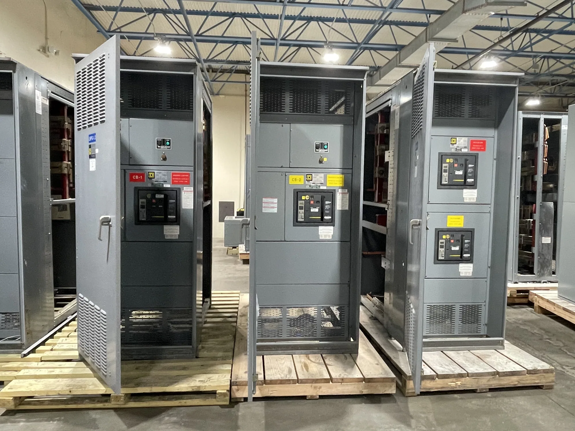
Start with the intended system and scope
To specify generator paralleling controls, provide enough information to define what sources will operate together, how they connect to the electrical system, and what the controls must do in each operating condition. Identify whether the project needs a new generator paralleling switchgear assembly, controls integrated with other equipment, or a defined controls scope within a broader package. Clarify equipment boundaries and who is responsible for each interface.
Include the project location, application, project stage, requested equipment delivery window and the responsible engineering contact. State whether the system serves standby, prime, peak-shaving, or another operating purpose, if known. These descriptions help frame the design, but they do not replace the actual sequence of operation, electrical documents or project-specific requirements.
Provide generator and electrical-system data
For every generator, provide the manufacturer and model if selected, nameplate information, voltage, frequency, phase, rated capacity, neutral and grounding arrangement, and available alternator or control-system documentation. Identify which details are preliminary and which are confirmed. Include generator breaker information and any required trip, close, status or permissive interfaces; the responsible engineer and equipment suppliers must verify compatibility.
Submit a one-line diagram showing generators, bus sections, utility or other sources, tie breakers, loads and connection points. Add available equipment schedules, load information, transformer data and protection requirements where applicable. Explain whether the design includes isolated or connected bus sections, closed-transition operation, utility paralleling, or other source transfers. Do not assume a configuration from a brief project description; the drawings and approved design criteria should establish it.
Describe the sequence of operation
Write the required sequence in plain language, covering normal operation, loss of source, generator start, synchronization, breaker closing, load connection, return to normal and shutdown. Specify which events initiate each action, what conditions must be satisfied, and what happens if a generator fails to start, synchronize or carry its assigned load. Include alarms, operator decisions, time delays and reset expectations when they are part of the intended operation.
For example, a facility might require multiple generators to start after a utility interruption, connect to a dead bus in a defined order, and add load in stages. Its preferred response to a failed unit, restoration of utility power, or a request for manual control can change the control logic and equipment interfaces. This is an illustrative scenario, not a recommended sequence: the project engineer must determine the safe, code-appropriate operation for the actual system.
Identify modes, priorities and load control
List required operating modes, such as automatic, manual, test, or maintenance modes, and explain who may select them and what functions remain available in each. State whether operators need local controls, remote commands, or both. Define generator dispatch priorities, lead-lag rotation, load sharing approach, load shedding or load adding requirements, and any limits that affect the operating plan. Confirm which behaviors are mandatory and which are preferences.
Paralleling controls may coordinate functions such as synchronization, breaker control, load sharing and system alarms, but the exact scope depends on the selected design. Identify protection functions and settings that must be coordinated with generator controls and the overall electrical system. Avoid treating a generic control description as a complete protective-relaying specification; protection responsibilities and interfaces must be explicitly assigned and reviewed by qualified project personnel.
Build the interface and communications point list
Provide a point list for each generator, breaker, utility interface, building automation system, and supervisory or remote monitoring system. For each point, describe its purpose, source, destination, signal type if known, required command or indication, and any alarm priority or operating consequence. Include hardwired signals and network communications separately, and identify required protocols or project standards for the responsible engineers to confirm.
Clarify who supplies network equipment, configuration, addressing, graphics, remote access and integration testing. Identify available drawings and documentation for existing systems, without assuming that a new controller will communicate seamlessly with them. Also state instrumentation needs, including measurements, display locations, event records and trends. A complete point list makes scope gaps easier to find before control hardware and wiring details are finalized.
Set testing, documentation and acceptance expectations
Describe the factory and field testing scope requested, the documents needed for review, and the parties expected to witness or approve each test. Ask the manufacturer to identify what can be demonstrated with the supplied assembly and what depends on generators, external breakers, site wiring or third-party controls. Define required submittals, such as control descriptions, drawings, point lists, operating manuals and test procedures, subject to project requirements.
Testing plans should trace back to the approved sequence and interface list: demonstrate intended modes, alarms, permissives, breaker commands and failure responses within the agreed scope. Site commissioning and any work involving electrical equipment must be performed by qualified personnel using applicable safety procedures. The project team should confirm acceptance criteria and responsibility for each test before ordering, rather than presuming every site condition can be reproduced at the factory.
Prepare a clear request for quotation
Before requesting a quotation, assemble the one-line diagram, generator data, sequence of operation, mode matrix, point list, protection and communications requirements, project schedule, and testing and documentation expectations. Mark open decisions and identify who will resolve them. Ask the manufacturer to state assumptions, exclusions, required customer-furnished information and any design-dependent items needing confirmation. Include equipment ratings and applicable standards only as established by the project specification.
With that information, a manufacturer can assess a custom-to-specification generator paralleling switchgear package and identify questions that affect scope. South Carolina Switchgear Builders manufactures new equipment in the United States and ships nationwide; configuration, availability and actual lead time depend on the order and must be confirmed. A coordinated specification gives the engineer, manufacturer, generator supplier and integrator a practical basis for resolving interfaces before final design and procurement.