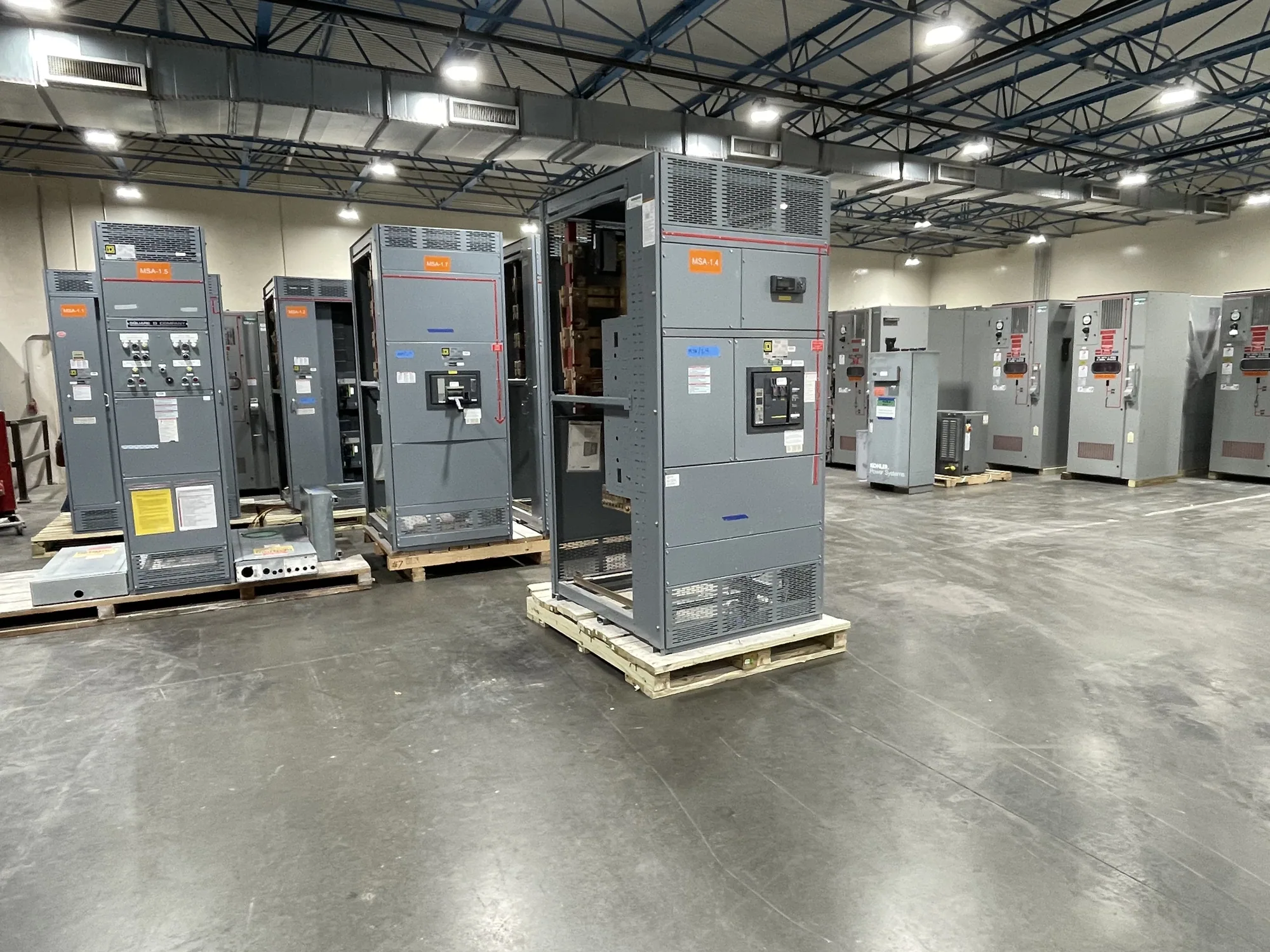
Redundancy changes the electrical arrangement
Data-center redundancy plans affect switchgear by defining how power reaches critical loads when a source, feeder, or piece of equipment is unavailable. The plan may call for separate power paths, alternate sources, or capacity that can support selected loads during an outage or maintenance event. Those objectives shape the lineup, bus arrangement, switching functions, protection scheme, and connections specified for the project.
There is no single switchgear configuration that makes a data center redundant. The owner and responsible engineer must define which failure or maintenance conditions the design should address, which loads need alternate supply, and whether paths are intended to remain electrically independent. Equipment can support that design, but equipment selection alone cannot establish a facility’s availability or guarantee uninterrupted operation.
Map sources, paths, and loads
Start with a one-line diagram showing utility sources, transformers, generators, transfer equipment, distribution buses, and major load groups. Identify where each normal and alternate path begins and ends. The engineer should clarify whether a bus tie is normally open or closed, what conditions permit its operation, and how the design prevents unintended paralleling or overload. These decisions affect breaker functions, bus sections, control logic, and required ratings.
Redundant paths can be physically or electrically separate, but the intended degree of separation needs to be explicit. Shared upstream equipment, common control power, or a common bus may create dependencies that are not obvious from equipment labels. Ask the project engineer to identify those dependencies and document the operating states to be supported. The switchgear manufacturer then needs the approved electrical and functional requirements to configure new equipment to specification.
Plan for maintenance and bypass functions
Maintenance provisions should be evaluated as part of the power-path design, not added as an assumed feature. A bypass arrangement may let a load receive power while a component is isolated, but the exact meaning of “bypass” varies by equipment and system. Confirm which device is bypassed, what alternate path carries the load, what interlocking or switching steps apply, and whether the remaining path has adequate capacity for the intended condition.
A bypass can also introduce operational tradeoffs. It may add equipment, connections, controls, and procedures; it can affect available fault current, protection coordination, or the ability to isolate a section. The engineer should determine whether the arrangement fits the facility’s maintenance strategy and operating procedures. Equipment details, including physical space, cable entry, access, and control interfaces, should be reviewed against the project layout before release for manufacture.
Coordinate protection and generator operation
Selective coordination is particularly important when alternate sources and multiple distribution levels are involved. Protective devices must be evaluated across the operating configurations the project expects, rather than only for one normal source path. Generator operation can change system conditions, and a tie or transfer sequence may change which devices are in series. The responsible engineer should provide the study assumptions and settings requirements for review with the specified equipment.
Generator paralleling switchgear may be part of a design that operates multiple generators together, but it is not automatically required by every redundancy plan. The project should define whether generators operate independently, in parallel, or in another approved sequence; how load is assigned; and what control and protective functions are required. Confirm interfaces with generator controls, transfer equipment, and downstream switchgear. Do not assume that a product name or generic diagram establishes compatibility.
Monitoring supports operation, not a guarantee
Monitoring requirements can influence metering, communications, control power, alarms, and terminal provisions. List the values and statuses the operations team needs to see, where they will be collected, and which external systems must receive them. Clarify communications protocols and responsibility for configuration with the project team. Monitoring can help personnel understand equipment state, but it does not itself provide a redundant path or assure availability.
Owner-defined objectives should be translated into specific design conditions. For example, an owner might want selected critical loads to remain supplied while one distribution section is isolated for planned work. The engineer must test that scenario against the one-line, equipment ratings, protection, switching sequence, and load assumptions. A different objective—such as accommodating a source outage—may lead to different equipment and control requirements. Neither scenario supports a general uptime promise.
Prepare a useful switchgear inquiry
For a project review, provide the current one-line diagram, system voltage and phase, source information, load schedule, available fault-current data, and required equipment ratings where established. Include normal and alternate operating configurations, generator and tie operating modes, protection-study requirements, physical dimensions, cable-entry preferences, control and monitoring points, and applicable project specifications. Clearly mark items that remain undecided so the engineer and manufacturer can identify what needs resolution.
Before approving a design, ask who owns the system studies, control logic, and interface checks; which operating scenarios have been reviewed; and how proposed bypass or tie arrangements affect the remaining path. Confirm equipment scope, applicable listing or testing requirements, and delivery expectations against the actual specification and order. New switchgear can be custom-built to specification, with availability and lead time confirmed for the project. Qualified personnel should handle installation, testing, and maintenance under applicable safety procedures.