Start with what the meter must help you decide
There is no universal metering-point list for every switchgear lineup. Include the measurements needed to understand incoming power, manage distribution, allocate energy, or investigate operating issues, and identify the equipment location for each point. The project engineer and owner should decide which measurements are required, which are useful, and which belong in another system.
For each metered circuit, consider whether operators need phase currents, phase-to-phase or phase-to-neutral voltages as applicable, frequency, real power, reactive power, apparent power, power factor, and accumulated energy. Specify only values supported by the selected meter and instrument-transformer arrangement. The one-line diagram, operating philosophy, and owner’s reporting needs should guide the final point schedule.
Define the point list by circuit and use
Build the schedule around incoming mains, tie breakers, feeders, or other monitored circuits rather than saying only “provide metering.” State the circuit identifier, measurement name, units, whether the value is instantaneous or accumulated, and whether it is required locally, remotely, or both. Mark required points separately from optional points so the supplier can identify the intended scope without guessing.
For a main, the owner might require current, voltage, demand, power, power factor, frequency, and energy. A feeder used for energy allocation may need a more limited set, while a critical load may need additional alarms or status signals. These are examples, not a standard package: confirm each point’s operational purpose, meter capability, and availability from the proposed design.
Specify accuracy and measurement boundaries
Accuracy requirements should reflect the decision being made. Operational visibility, internal energy tracking, and billing or settlement can have different requirements. Identify the applicable accuracy class or project performance requirement for meters and associated current and voltage transformers, where used. The responsible engineer must confirm that the complete measurement chain—not just the meter display—can meet the intended need.
Also document where each measurement begins and ends. A meter on an incoming section does not automatically account for downstream losses or provide a separate value for every branch. Decide whether readings represent a source, a bus, a feeder, or a defined load boundary. Confirm transformer ratios, wiring assumptions, and units against the approved electrical design and equipment configuration.
Plan communications and owner integration
State how data should reach the owner’s monitoring or energy-management system. Specify the required protocol, physical interface, network arrangement, point naming convention, data update expectations, and who supplies any gateways or network components. If the owner has a standard, provide its revision and identify the party responsible for mapping, configuration, and connection details. Do not assume that a meter’s communications port guarantees compatibility with the complete system.
Separate measured values from breaker status, alarms, and control functions. They may share an interface, but they are distinct requirements and can involve different devices or project responsibilities. Identify whether data must be available at a local display, through a communications network, or both. Address cybersecurity and network segmentation through the owner’s approved requirements rather than leaving those decisions to an unspecified default.
Consider a practical project scenario
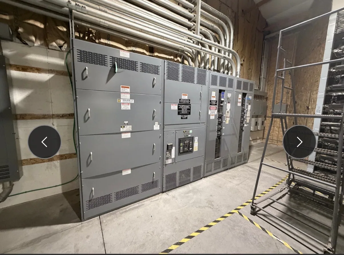
For a data center lineup, an owner may want incoming measurements for overall supply visibility and selected feeder energy values to compare major load groups. That does not mean every feeder needs an identical meter or that all values belong in a building-management system. The design team should map each requested point to a circuit, operating use, display location, and receiving system before finalizing the equipment schedule.
A frequent misunderstanding is to request “full metering” without defining points, accuracy, or communications. Another is to treat a meter’s advertised functions as proof that the proposed assembly will deliver every value in the required format. Ask the manufacturer and project engineer to verify the meter selection, instrument-transformer details, physical space, wiring, and interface against the actual specification.
Make acceptance and submittals testable
State how metering will be checked during project acceptance and who performs each check. Depending on the agreed scope, verification may include confirming meter configuration and displayed values, checking point names and units, and demonstrating communications to an agreed test endpoint. Define the test method and acceptance responsibility in advance; do not assume that factory checks, field commissioning, and owner-system integration are the same activity.
Review submittals for the point schedule, meter and transformer data, wiring diagrams, communications details, and any required interface components. Record exceptions or proposed substitutions for review before approval. Testing and installation activities should be carried out by qualified personnel under applicable safety procedures. The project documents should make clear which results are required and who reviews them.
Questions to resolve before issuing the specification
Before requesting a proposal, ask: Which circuits require measurement? Which values are essential on each circuit? Are readings for operations, energy allocation, or another defined purpose? What accuracy is required, and at what measurement boundary? Which protocol and network responsibilities apply? What points must be demonstrated, by whom, and at which project stage?
Provide the one-line diagram, circuit schedule, metering-point list, applicable owner standards, and integration requirements with the equipment inquiry. Identify any open decisions rather than implying they are settled. A complete, project-specific scope lets the manufacturer review the requested configuration and flag details that need engineering confirmation before the switchgear design and submittals are finalized.