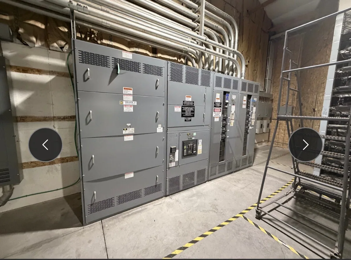
Start with the room and equipment scope
To plan indoor switchgear, provide a dimensioned room plan, the equipment’s electrical requirements, the route from delivery point to final position, and details about the room’s environment and intended maintenance access. These inputs help the manufacturer and project team assess whether a proposed lineup can be configured and installed in the available space. They do not replace the responsible engineer’s design review or confirmation of code requirements.
Identify the equipment type and intended use: for example, whether the project needs a low-voltage switchboard or medium-voltage switchgear, and whether it is new construction or a replacement in an existing room. Share the project drawings and current specifications, including any known lineup arrangement, connection requirements, or interfaces with other equipment. If some details remain undecided, label them as open items rather than treating assumptions as final.
Room dimensions and obstructions
Provide the room’s clear inside dimensions and ceiling height, with the proposed equipment location and orientation marked. Include columns, beams, alcoves, raised floors, trenches, housekeeping pads, floor openings, stairs, and other features that may affect placement. A simple sketch can help start the discussion, but scaled architectural or electrical drawings give the project team a more reliable basis for coordination.
Show doors, door swings, wall openings, and the locations of nearby equipment or building systems. Note items such as piping, ductwork, cable trays, lighting, sprinkler components, and ceiling services wherever they could conflict with the lineup or access for work. Record dimensions to fixed reference points when possible. The required clearances and final equipment arrangement must be confirmed for the specific design and applicable project requirements.
Working space and operating access
Room planning must account for people as well as equipment. Show the intended operating side, adjacent walls, and the space available for inspection, operation, and maintenance. Identify doors or other obstructions that could restrict access to controls or prevent equipment sections from being opened or serviced. Do not assume that an empty rectangle around the lineup automatically satisfies applicable working-space requirements.
Ask the project engineer to confirm required working clearances, access provisions, and any egress considerations for the specific installation. Also discuss how cables enter and leave the equipment, where connections are expected, and whether the proposed routing can be coordinated with other systems. These questions can affect lineup orientation and room layout; resolving them early is generally more practical than discovering a conflict after construction or equipment delivery.
Delivery route and final placement
The room’s dimensions alone do not establish that equipment can reach it. Document the complete route from the receiving point to the final location, including loading areas, corridors, doors, turns, ramps, elevators, floor transitions, and any temporary construction openings. Provide clear widths and heights at the tightest points, plus known limits on floor loading or handling access for the project team to review.
For example, a room may appear large enough on plan while a narrow corridor or sharp turn prevents a planned section from passing through. That possibility may affect how the lineup is arranged or delivered, but the appropriate solution depends on the equipment design and confirmed handling plan. Share delivery constraints and construction sequencing with the manufacturer early. Equipment configuration, shipment details, and delivery timing require project-specific confirmation.
Environmental and building conditions
Describe the conditions expected in the room during operation and, if relevant, during construction or temporary storage. Provide available information about temperature, moisture, condensation risk, dust, corrosive substances, ventilation, and possible water exposure. Note whether the room is conditioned, whether environmental controls are planned, and whether other heat-producing equipment will share the space. Avoid assuming that an indoor location is automatically suitable for every equipment configuration.
Tell the responsible engineer about known heat or ventilation concerns and ask what information is needed to evaluate them. The room’s environmental conditions may influence equipment selection or project provisions, but acceptable conditions and any required mitigation must be verified against the actual specification. Share site-condition details alongside drawings rather than relying on a general description such as “clean, dry room.”
Maintenance, coordination, and buyer checklist
Explain how the owner expects qualified personnel to inspect, operate, and maintain the equipment, and identify any access or removal constraints that the project team already knows. Confirm who is responsible for coordinating architectural dimensions, electrical clearances, cable routing, environmental provisions, and equipment interfaces. Provide the latest drawings and identify their revision dates so reviewers can distinguish current information from preliminary layouts.
- What are the room’s clear dimensions, ceiling height, and fixed obstructions?
- Where are the doors, delivery openings, and complete equipment access route?
- What working and maintenance clearances should the project engineer verify?
- What environmental conditions, ventilation plans, and floor constraints are known?
- What equipment type, electrical requirements, cable routes, and interfaces are specified?
- Which layout details remain preliminary, and who will approve the final arrangement?
Send the available room drawings, site-condition information, and open questions with the equipment inquiry. A manufacturer can use that information to discuss a new, custom-to-specification configuration, while the project engineer confirms design requirements and the construction team coordinates the room and delivery route. Availability and actual lead times depend on the order and must be confirmed. Clear, current inputs give everyone a stronger basis for resolving fit and coordination questions before the project advances.