How to use this switchgear glossary
Electrical distribution documents use concise terms that can carry specific technical meanings. This glossary introduces common concepts and shows how they connect to equipment selection. It is a starting point for conversations, not a substitute for the project drawings, applicable standards, or decisions made by the responsible engineer.
A definition can also depend on the equipment type and the standard named in a specification. A term used for a low-voltage switchboard may not describe a medium-voltage switchgear assembly in the same way. When reviewing a quote or design, use the project’s stated terminology and ask for clarification wherever a definition, rating, or boundary is unclear.
Distribution equipment and system layout
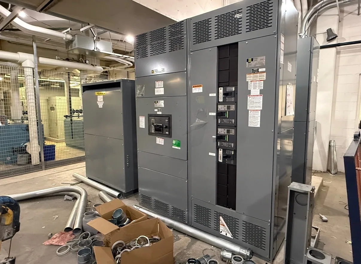
Switchgear is an assembly of electrical switching and protective devices, arranged to control, protect, and isolate portions of a power system. The precise construction and applicable requirements depend on its voltage class and design. Switchboards are low-voltage distribution assemblies that combine devices such as breakers, bus, and metering in a coordinated structure. The two product names are related, but should not be treated as interchangeable.
A single-line diagram is a simplified representation of an electrical system. It shows sources, distribution paths, protective devices, and major loads without drawing every conductor separately. Buyers can use it to communicate the intended arrangement, but the diagram needs to be current and coordinated with the project specification. Changes in sources, loads, or downstream equipment can affect the required configuration.
A lineup is the group of connected equipment sections arranged as one installation. Section count, order, access, cable entry, and site space can influence the physical design. Confirm dimensions and interface details against the available room and installation plan rather than assuming a standard arrangement will fit. The intended sequence of sections should be clear in the drawings and purchase documents.
Ratings, capacity, and available fault current
Voltage class identifies the broad operating class of the equipment. A 480 V class assembly is low voltage; 5 kV and 15 kV classes are medium voltage. These labels do not establish every required rating. The project team must confirm the actual system voltage and equipment specifications, including which components and assembly ratings apply to the proposed design.
Available fault current is the prospective current that could flow at a point in the system during a fault, based on the system configuration and source conditions. It is important when evaluating equipment interrupting and withstand capabilities. Its value is not safely inferred from a building type or a nearby device label. The responsible engineer should provide or confirm the applicable fault-current information for the equipment location.
Continuous current rating describes the current an assembly or component is intended to carry under specified conditions. Short-circuit ratings address performance under fault conditions, and must be understood in relation to the assembly, protective devices, and system. Do not compare ratings by number alone: verify the exact rating basis, configuration, and documentation required for the project.
Protection, switching, and control terms
A circuit breaker is a switching device that can interrupt current under specified conditions and may operate in response to protective settings. A trip unit is the part of a breaker that evaluates current and initiates a trip according to its design and settings. Selection involves more than choosing a breaker size; coordination, load needs, available fault current, and downstream equipment all matter.
Selective coordination describes arranging protective devices so that, where required and feasible, the device nearest a fault operates before upstream devices. Engineers evaluate device characteristics and system conditions to determine whether a proposed arrangement meets project objectives. A coordination study or specified settings may inform the equipment design, but glossary definitions alone cannot establish the right settings for a particular installation.
Bus, or busbar, is a conductive path that distributes power among equipment sections or connected circuits. Metering refers to instruments and associated components used to observe electrical quantities. Control wiring carries signals for functions such as indication, operation, or interlocking. These terms describe different parts of an assembly; their required locations, functions, and interfaces should be explicit in the drawings and specification.
Standards, listings, and design verification
A standard sets requirements for a defined category of equipment or activity. A listing is a product certification status tied to a specific evaluated design and scope. For eligible low-voltage switchboards, UL 891 may apply, but applicability and assembly listing must be verified for the specific design. It does not apply as a blanket claim to medium-voltage switchgear or to every distribution assembly.
Review the project’s required standards, listing language, and documentation with the responsible engineer and manufacturer before ordering. A broad phrase such as “code compliant” does not identify the actual requirements or prove that a particular configuration satisfies them. Confirm which edition or project requirement governs and whether requested options affect the evaluated assembly.
Using terminology to make project decisions
Definitions help teams ask better questions, but do not replace engineering review. For example, a higher short-circuit rating may affect component selection and assembly design, while access, cable termination, or metering needs can shape the physical layout. Weigh these requirements against the one-line diagram, available installation space, operating goals, and project documents instead of optimizing one specification in isolation.
When a term appears inconsistent across documents, identify the exact drawing, schedule, or specification note and request a written resolution. Clarify whether the requirement applies to the full assembly or a particular component. This simple discipline can reduce ambiguity between design intent, the equipment quote, and installation coordination without treating a glossary entry as authorization to alter the design.
Information to prepare for a new equipment request
Useful starting information includes the equipment type and voltage class, current single-line diagram, applicable ratings, available fault-current information, required protective devices, metering and control functions, and any project-specific standards or listing requirements. Add the desired section arrangement, cable entry details, site constraints, and requested accessories where known. Mark unresolved items clearly so the engineer and manufacturer can identify decisions still needed.
South Carolina Switchgear Builders manufactures new switchgear and switchboards to specification, with US-built equipment, all-American components, and nationwide shipping. Configuration, availability, applicable listings, and delivery timing depend on the order and must be confirmed. Clear terminology and complete project documents help the manufacturer review the requested design and coordinate open questions before the equipment is finalized.
Use glossary definitions to orient the discussion, then verify each requirement against the project specification and responsible engineering review. A well-defined request connects system drawings, ratings, protection, physical interfaces, and documentation into one coordinated scope. That gives the project team a more reliable basis for evaluating new equipment and resolving technical questions before purchase and installation.