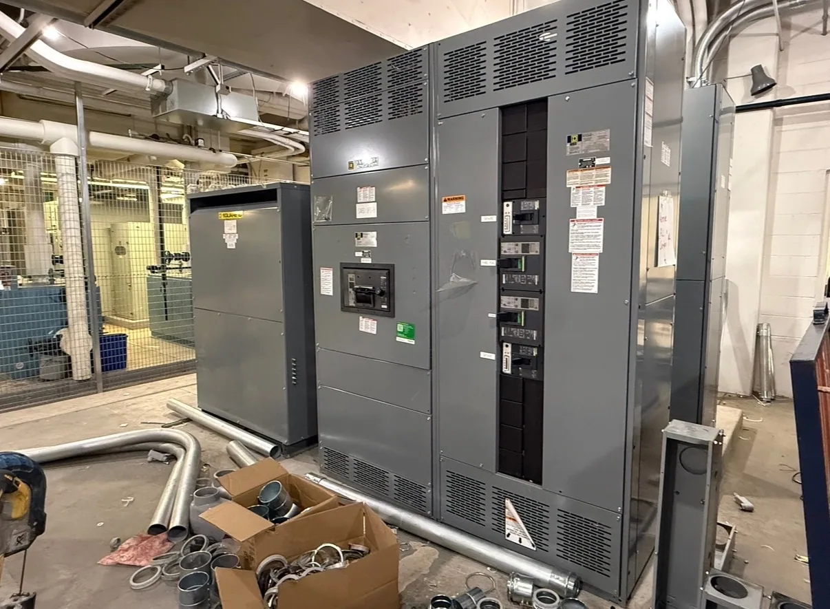
What bonding means
In electrical distribution, bonding is the act of establishing electrical continuity between conductive parts for an intended safety purpose. A bond provides a deliberate conductive connection where the design requires parts to be electrically connected. The term describes an electrical relationship, not simply the presence of metal-to-metal contact or a general connection to earth.
Bonding is related to grounding, but the words do not mean the same thing. Grounding connects a system or equipment to ground as specified by the design and applicable rules. Bonding connects conductive parts to one another or to a designated point in the system. A project may require both, with each connection serving a defined role.
Why the distinction matters
Conductive enclosures, frames, doors, raceways and other metal parts may need bonding so they are connected as intended. The exact method depends on the equipment construction and system design. A project engineer determines which parts require continuity and how that continuity is established; a buyer should not infer the answer from appearance alone.
Bonding is also important to how a fault-current path is considered. If a fault connects an energized conductor to a conductive enclosure, the intended path and protective-device response depend on the complete system. Bonding provisions are only one element of that design. They do not replace overcurrent protection, grounding conductors, safe installation, or inspection by qualified personnel.
Switchboards, neutral treatment, and system arrangement
For a new switchboard, bonding questions should be settled in relation to the service or feeder arrangement, not by applying one rule to every installation. The neutral conductor’s treatment, the location of any required system connection, and the equipment grounding path are design matters. The responsible engineer should identify the applicable arrangement and specify the required connections for the particular project.
For example, consider a conceptual project in which a new switchboard receives a feeder from upstream equipment. The assumption here is only that it is feeder-supplied; no voltage, source type, or grounding method is presumed. The project team must determine whether the neutral is present and how it is treated, which conductive parts require bonding, and where the grounding path is established. Those answers belong in the project documents and equipment specification.
Common misinterpretations
A common error is to use “bonding” and “grounding” interchangeably. Another is to assume that any connection to earth automatically creates the intended bond between equipment parts. A third is to assume the neutral should be connected to an enclosure wherever a switchboard is installed. Neutral-to-ground connections are system-dependent; their location and arrangement require review by the project engineer.
Bonding is not the same as an equipment grounding conductor. The conductor may form part of an equipment grounding path, while bonding describes the connection or electrical continuity required among parts. Related glossary terms can help distinguish those concepts. For project-specific requirements, a grounding-and-bonding specification guide addresses the information needed to define the design rather than just the vocabulary.
What to confirm in a project specification
Before requesting a new switchboard, provide the supplier with the project’s one-line diagram and the electrical engineer’s requirements for source, service or feeder arrangement, neutral, and grounding. Identify the intended application, equipment scope, and any relevant drawings or specifications. If details are preliminary, label them as such and ask which decisions must be resolved before the equipment design can be confirmed.
Ask how the specified bonding provisions will be represented in the proposed equipment, what connection points or accessories are included, and which project documents govern. Confirm that enclosure and internal component details match the approved design. Listing, ratings, testing, and standards applicability must be checked for the actual assembly and specification; they should not be assumed from the word “bonding” or from a product category.
Coordinate design, supply, and installation
Review the switchboard submittal against the engineer’s documents before approval, paying particular attention to any changes in the source arrangement, neutral requirements, or equipment scope. Resolve discrepancies in writing with the engineer and manufacturer. This coordination helps keep the specified bonding approach consistent with the intended system instead of relying on an informal assumption during installation.
Equipment supply does not determine field wiring or authorize work on energized equipment. Installation, verification, testing, and maintenance should be performed by qualified personnel under applicable project procedures and safety requirements. When the system arrangement changes, the design should be reviewed rather than carrying forward bonding details from an earlier configuration.
Questions to take forward
Useful questions include: Which conductive parts must be bonded? What is the project’s service or feeder arrangement? How is the neutral treated, and where is any required system connection located? What grounding path does the engineer specify? Which drawings and standards govern the equipment, and what must be confirmed for the supplied assembly? Clear answers support a coherent equipment specification and an informed review.
Bonding, in short, means establishing electrical continuity between conductive parts for a defined purpose. Its practical meaning becomes precise only when tied to the system arrangement, equipment design, and project documents. Use the term to ask focused questions, then rely on the responsible engineer and the approved specification to establish what the new distribution equipment must provide.