Define the scope before specifying equipment
Grounding and bonding are related but distinct parts of an electrical distribution design. Grounding connects designated system points to earth; bonding joins conductive parts to establish the connections required by the design. Equipment grounding, neutral treatment and service arrangements must be considered together, not selected as isolated options on a switchgear schedule.
This guide addresses those coordination questions for new switchboards and metal-enclosed switchgear. The exact arrangement depends on the system design, equipment configuration and applicable code. It is not possible to prescribe one grounding method for every project from a product description alone. The responsible electrical engineer should establish the system requirements and confirm how they apply to the equipment being specified.
Start with the distribution system
Before requesting a proposal, provide the project’s one-line diagram and identify the source, nominal system voltage, phase and wire arrangement, grounding method and service point. Clarify whether the equipment is service equipment or downstream distribution, and describe the intended neutral-to-ground relationship at each relevant point. If any input is preliminary, label it clearly so the design can be reviewed against the final system.
Also share available fault-current information, protective-device coordination requirements and the project’s governing code basis when known. These inputs can affect equipment design and application, but no general product statement establishes a suitable rating or code outcome. The engineer must determine which values and rules apply to the project, and the proposed assembly must be checked against the actual specification before acceptance.
Coordinate grounding and bonding details
Specify how equipment grounding conductors, grounding bus provisions and bonding connections are to be arranged, identifying interfaces with upstream and downstream equipment. State any project requirements for conductor material, size, termination, routing or connection points only when established by the design. The equipment drawing review should make the intended connections legible and allow the project team to resolve interface questions before release.
Neutral treatment merits separate attention. Identify whether a neutral is required, how it is to be isolated or bonded in the specified equipment, and where the system design places any neutral-to-ground connection. The correct answer depends on the service and distribution arrangement; simply requesting a neutral bus does not fully describe its relationship to the enclosure or grounding system. Have the responsible engineer verify each connection against the project design and applicable code.
Evaluate the equipment in context
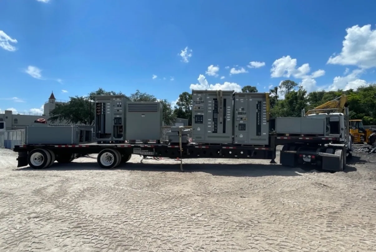
Consider a project with an electrical switchboard at a service or distribution point and metal-enclosed switchgear serving another part of the system. The equipment may have different functions and interfaces, so a grounding detail appropriate to one lineup should not automatically be copied to the other. The one-line diagram, equipment location and system arrangement should show how each assembly fits into the overall grounding and bonding design.
For each lineup, confirm the specified voltage class, intended use, neutral requirements, grounding provisions, connection points and relationship to adjacent equipment. Ask the project engineer to resolve any difference between drawings, schedules and written specifications. The manufacturer can review the requested equipment configuration, but system grounding decisions and code interpretations belong with the project’s responsible design professional. Confirm that proposed drawings reflect the approved design before manufacturing proceeds.
Resolve trade-offs and interfaces early
Grounding provisions can affect bus arrangement, enclosure details, cable entry and the space available for terminations. A more detailed connection requirement may improve coordination across the project, while an incomplete or changing requirement can prompt drawing revisions. Balance the need for a clear, buildable specification with the design team’s responsibility to determine the required connections and conductor details.
Coordinate equipment interfaces with the electrical contractor, engineer and other relevant project participants. Confirm who provides field conductors and connections, where those connections terminate, and which details are part of the equipment scope. If communications or instrumentation interfaces share routing or enclosure space, document them separately and coordinate the physical arrangement. Installation, inspection, testing and maintenance should be performed by qualified personnel following applicable safety procedures.
Prepare a useful equipment specification
A clear request should include the one-line diagram, equipment schedules, voltage and system configuration, service designation, neutral treatment, grounding and bonding requirements, available fault-current data, and applicable project specifications. Include connection and interface drawings when available, plus the expected operating environment and any installation constraints that could affect the equipment layout. Identify open design questions instead of silently assuming an answer.
Request drawings that show relevant grounding bus and bonding details, neutral arrangements, connection points and interfaces with adjacent equipment. Ask the design team to review the submittal against the one-line diagram and written requirements, then document approved changes. Listing, testing, ratings and standards are specific to the proposed assembly and must be confirmed against its actual design and documentation; do not treat a general statement as proof of project suitability.
Confirm decisions before release
Before approving equipment for manufacture, verify that the responsible engineer has confirmed the grounding method, neutral connections, service arrangement and applicable code basis. Check that the approved drawings identify the intended bonding and equipment-grounding connections and agree with the latest project documents. Resolve discrepancies in writing, including responsibility for field connections and any remaining design assumptions.
South Carolina Switchgear Builders manufactures new equipment to specification, with US-built equipment, all-American components and nationwide shipping. Availability and actual lead times depend on the order and must be confirmed. Provide a coordinated, current specification for review so the proposed switchboard or metal-enclosed switchgear can be evaluated against the project’s documented grounding and bonding requirements.