What a busbar is
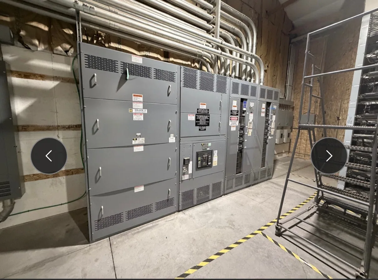
A busbar is a conductive component or arrangement that carries electrical power and distributes it among circuits within an assembly. In switchgear or a switchboard, incoming power may connect to a bus system, which in turn supplies connected protective devices and outgoing circuits. The busbar is part of the equipment’s current path; it is not, by itself, the complete switchgear assembly.
Busbars can be made from conductive materials such as copper or aluminum, with form and layout selected for the equipment design. The term describes a function and a component arrangement, not one universal shape, material, or rating. A bus system may include multiple conductors to accommodate the phases and, where the design calls for them, neutral or grounding functions.
Where the term fits in low-voltage equipment
In low-voltage switchgear, busbars provide a common distribution path between the incoming section and equipment serving downstream circuits. Their placement and connection points influence how the assembly is arranged and how power reaches individual devices. The exact architecture depends on the project specification and equipment design; a glossary definition cannot establish a suitable configuration for a particular installation.
A busbar should also be distinguished from a main bus. “Busbar” names the conductive component or system. “Main bus” identifies a particular bus function within an assembly: the common distribution path serving other sections or circuits. Drawings and specifications should use these terms consistently so that the intended conductor arrangement and connections are clear.
Design factors that affect selection
Material and cross-section are considered in relation to the required current, operating conditions, physical space, and assembly design. A larger conductor is not automatically the right answer: layout, connection details, thermal behavior, and mechanical support all matter. The responsible project engineer and equipment supplier should confirm the proposed design against the actual requirements rather than infer a busbar size from a general definition.
Fault-current forces can place mechanical stress on conductors and supports. Bracing and spacing therefore need to suit the specified system conditions and the assembly construction. Temperature rise is another design consideration, influenced by conductor characteristics, joints, enclosure conditions, and current. Project-specific ratings and performance depend on the complete design and must be confirmed for the supplied equipment.
Joints and connections deserve explicit attention because they form part of the electrical path. The design must account for how bus sections connect, how interfaces align, and how any required access or maintenance is handled by qualified personnel under applicable safety procedures. If the assembly’s location or operating environment affects expansion or movement, ask the responsible engineer whether the design must accommodate it.
A conceptual project example
Consider a project team planning a new low-voltage switchgear lineup for a facility. At an early stage, the team knows that the assembly will receive power and distribute it to several outgoing circuits, but has not finalized conductor arrangement or ratings. The busbar discussion then becomes a coordination task: define what the assembly must supply, document the intended configuration, and have the responsible parties confirm the design.
This example does not imply a particular current, fault rating, material, or assembly layout. Those details depend on project information that is not captured by the word “busbar.” Nor does specifying a busbar alone establish that an assembly meets a particular standard. For eligible low-voltage switchboards, UL 891 applicability and any assembly listing must be verified for the specific design; that standard should not be casually applied to all switchgear.
Common misunderstandings and related terms
A busbar is not the same as a cable, although both can conduct and distribute electricity. It is also not synonymous with a complete switchboard or switchgear lineup. Busbars are components within equipment, and their design has to be considered alongside protective devices, enclosure arrangement, connections, and the assembly’s overall specification.
Likewise, the phrase “busbar rating” should not be treated as a standalone answer to whether equipment is suitable. Buyers and engineers need to confirm the applicable system requirements and the complete assembly details. Terms such as bus section, main bus, and branch connection describe related functions or arrangements, but their exact meaning in a project should be established by the drawings and specification.
Information to confirm before ordering
For a new equipment inquiry, provide the intended application, system information, incoming and outgoing circuit requirements, desired lineup arrangement, and project drawings or specifications when available. Identify any known installation constraints and the questions that remain open. The manufacturer can then review the requested configuration and clarify what information is still needed before design, availability, and delivery details are confirmed.
- What electrical and operating requirements must the assembly meet?
- Which bus arrangement, material, connections, and section interfaces are specified or still under review?
- What project drawings, equipment interfaces, and installation constraints should be coordinated?
- Which ratings, testing, listing, and standards are required and need confirmation for the specific assembly?
Busbar is the vocabulary starting point; the specification turns that concept into a coordinated equipment design. Resolve open technical questions with the project engineer and supplier, and confirm the final requirements against the supplied assembly before purchase and installation planning.