What a potential transformer means
A potential transformer (PT), commonly called a voltage transformer (VT), is an instrument transformer that provides a scaled voltage signal for measurement, metering, or protection. Its primary winding connects to the electrical system, while its secondary delivers a lower, proportional voltage to suitable instruments or relays. The signal lets those devices represent system voltage without connecting their sensing inputs directly to the primary circuit.
A PT is a sensing device, not a general-purpose power transformer intended to supply loads. Its design and selected accuracy, insulation, burden, and connection depend on the application and equipment. The project engineer should identify the applicable electrical design requirements and confirm that the particular transformer and assembly are suitable. Terms and conventions can vary; drawings and equipment documentation should make the intended function clear.
How PT signals support metering and protection
Metering equipment uses voltage signals to indicate or record system conditions. Protective relays may use voltage alongside current inputs to identify conditions or calculate quantities relevant to a protection function. A PT does not, by itself, decide whether a breaker should operate. The relay logic, settings, sensing connections, and breaker control circuit together determine the response, subject to the approved protection design.
That distinction matters when selecting protective relays. The engineer needs to match the relay’s required voltage inputs and functions to the PT arrangement, including phase connections and any neutral or ground reference needed by the scheme. The PT ratio and polarity must be represented correctly in wiring documents and relay configuration. A mismatch can produce misleading measurements or undermine the intended protection logic, so the complete sensing path requires review.
Connections, loading, and equipment interfaces
PT selection involves more than choosing a ratio. The responsible designer must consider system voltage, insulation coordination, grounding method, phase configuration, intended measurement or protection functions, and the combined burden of connected devices. Fuse arrangements, disconnecting provisions, secondary grounding, and wiring practices also depend on the application and applicable design requirements. These choices should be settled in the project documents rather than inferred from the phrase “potential transformer.”
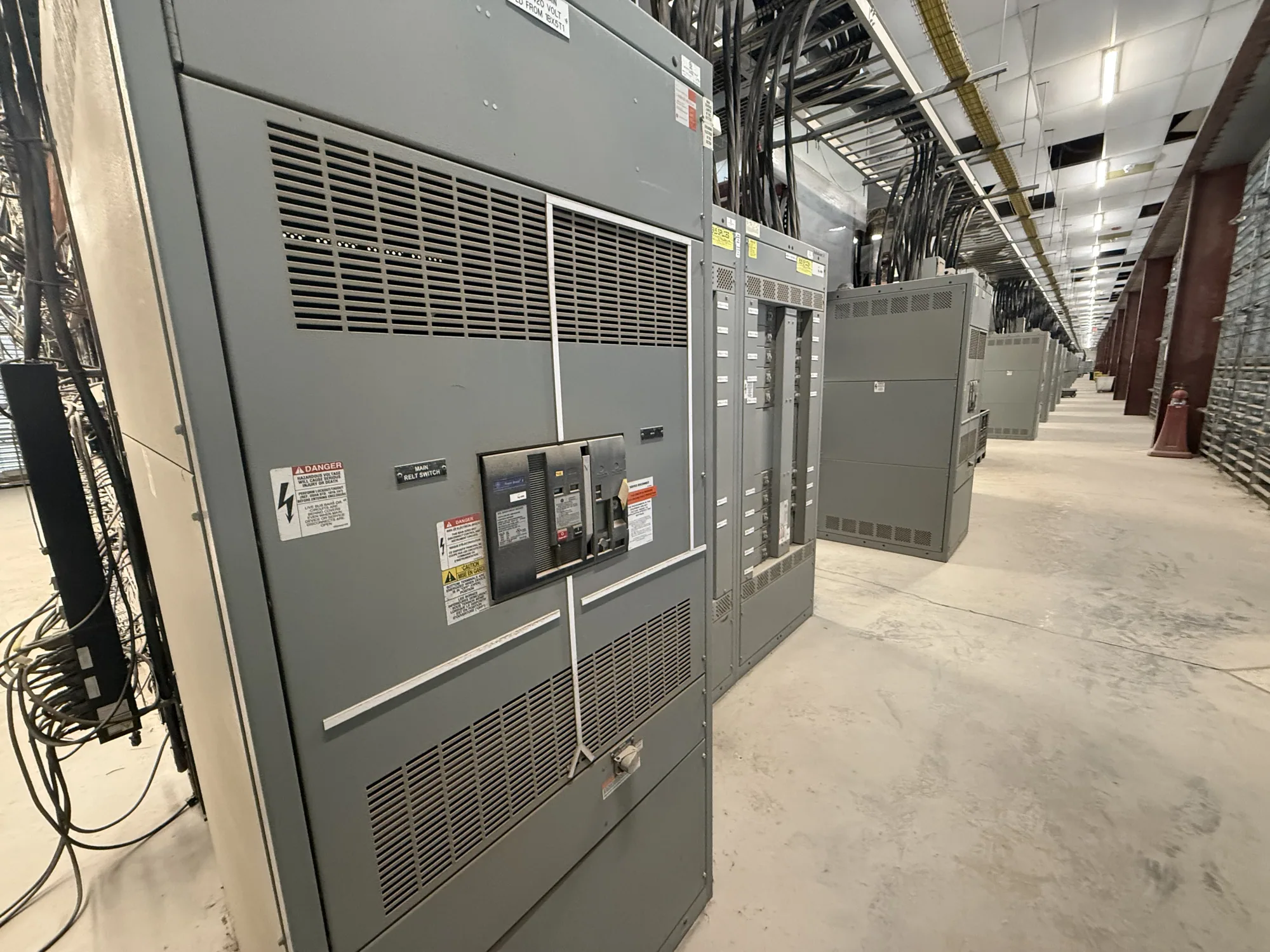
For an illustrative low-voltage switchgear project, a designer might consider voltage sensing for metering or a relay function within a new assembly. This example does not establish that every low-voltage switchgear lineup contains PTs or that a particular configuration is appropriate. The buyer should identify the required sensing points and relay functions, then ask the equipment manufacturer to confirm the proposed interface against the approved one-line diagram, control schematics, and project specification.
Conceptual example and common confusions
Assume a facility design calls for a relay to monitor voltage at a designated point in a distribution system. The engineer specifies a PT arrangement that converts the system voltage into a signal compatible with that relay, then documents the ratio, connections, grounding, and wiring. The relay’s settings and logic are coordinated with the protection scheme. No particular ratio or rating follows from this example; those values must come from the actual system design.
A PT is not a protective relay, a circuit breaker, or a control-power transformer simply because each may appear in the same equipment lineup. The PT supplies a measurement signal; the relay evaluates inputs; and the breaker interrupts a circuit when operated by its control system. A control-power transformer has a different intended role. Project drawings should name each device by function and show how its primary and secondary circuits connect.
Information to confirm before specifying
Before requesting new equipment, provide the system voltage and configuration, the PT’s intended measurement or protection purpose, the sensing location, and the relay or meter models when known. Include the one-line diagram, relevant schematics, grounding approach, required accuracy or burden criteria, and any specified enclosure or environmental conditions. Identify which decisions remain open so the engineer and manufacturer can resolve them without treating assumptions as approved requirements.
Ask who is responsible for selecting the ratio, confirming insulation and application suitability, defining secondary protection and grounding, and checking relay settings against the PT connections. Also clarify how the PT is to be mounted and wired within or alongside the equipment, what documentation is required, and which project standards apply. Availability, configuration, ratings, and any listing or testing details must be confirmed for the actual proposed design.
Coordinate the sensing design with the equipment
A clear PT specification connects the sensing function to the complete distribution design. Review the proposed arrangement with the project engineer and equipment supplier before drawings are finalized, especially when protection functions, metering, or switchgear interfaces are changing. For a low-voltage switchboard or switchgear application, confirm the equipment category and applicable requirements rather than assuming that standards or construction details carry over between product types.
After approval, keep the PT ratio, polarity, terminal identification, grounding, and relay configuration consistent across equipment documents and commissioning records. Installation, testing, and maintenance should be performed by qualified personnel following applicable safety procedures; never treat a glossary definition as a field procedure. When those responsibilities and interfaces are documented, the PT’s purpose is easier to verify from design through operation.