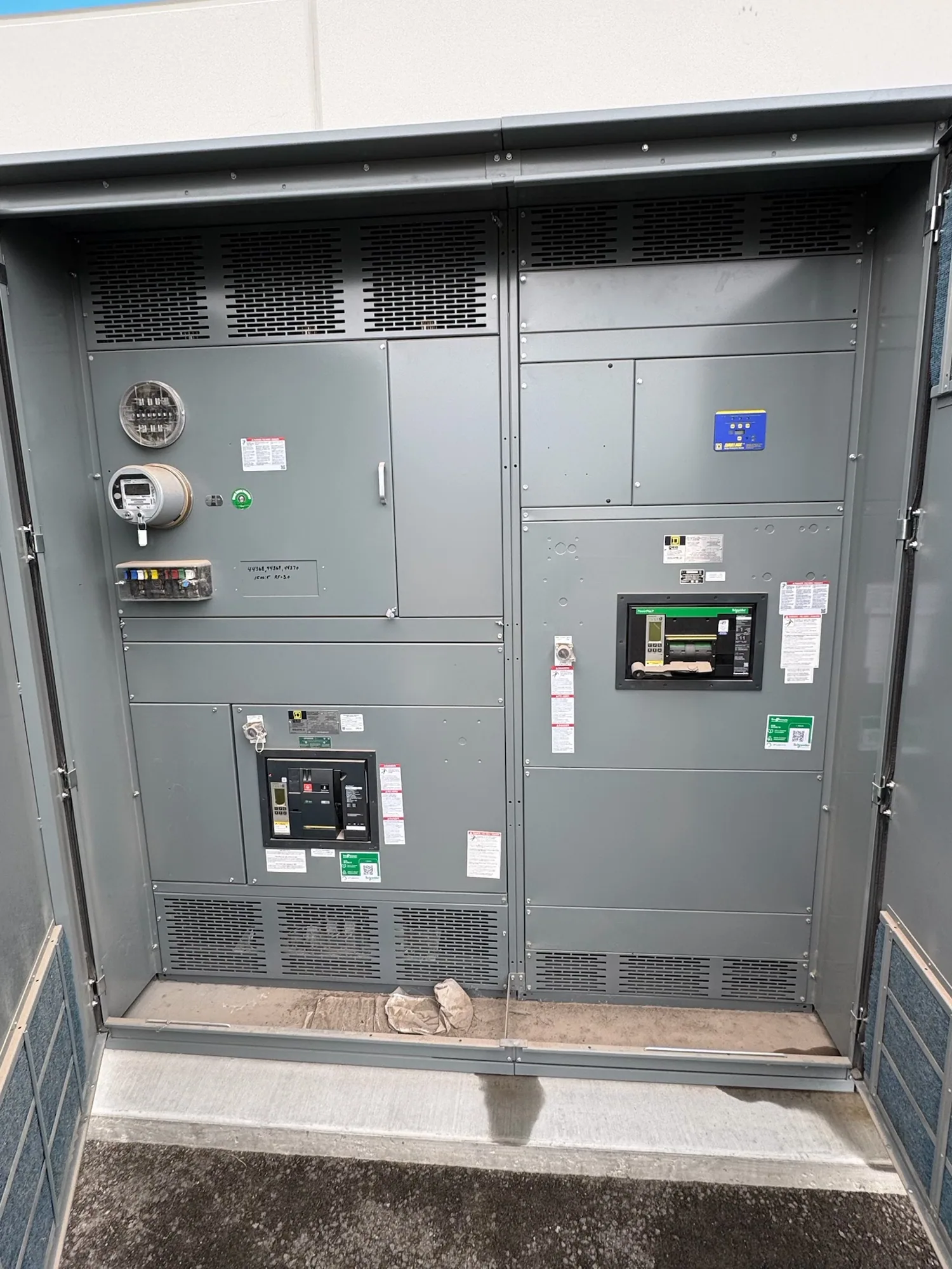
Define what the relay must protect
Protective relay selection starts with the system’s protection objectives, not a preferred device model. Identify the equipment and conductors in each protection zone, the abnormal conditions that require a response, and the intended action: alarm, trip, or both. The responsible engineer determines those objectives from the one-line diagram, system study, equipment characteristics, and applicable project requirements.
A relay is one part of a protection scheme. Breakers, current and voltage sensing, trip circuits, communications, and upstream or downstream devices affect how that scheme operates. Specify the required functions and interfaces rather than assuming that a relay’s feature list alone establishes suitable protection. Confirm the final design against the actual equipment and system conditions.
Start with system and equipment data
Provide a current one-line diagram and identify the distribution voltage class, source arrangement, grounding method, transformer data, connected loads, and anticipated operating configurations. Include available fault-current information and the studies or calculations the engineer will use. These details influence which conditions a scheme must detect and how its operation relates to other protective devices.
Describe the switchgear or switchboard position where the relay will be applied, including the associated breaker and the intended sensing arrangement. State the project’s operational priorities, such as selective isolation, continuity for critical loads, alarms, or remote indication. If system configurations can change, identify them; settings suitable for one arrangement may not be suitable for another.
Specify protection functions and sensing
List required protection functions by purpose and equipment zone, then have the responsible engineer determine the applicable functions and implementation. Function names or numbers can help communicate intent, but they do not replace a complete scheme description. Ask which conditions initiate an alarm or trip, what equipment receives each command, and whether any functions depend on system state or external inputs.
For each sensing input, document what is measured, its source, and the interface expected by the selected relay. Confirm current- and voltage-transformer characteristics, polarity, ratios, accuracy needs, and wiring requirements against the design and device documentation. Do not assume existing sensing devices are compatible or adequate. The engineer should verify the input range and burden requirements for the specific relay and connected instruments.
Resolve control power and trip interfaces
Control power is a selection constraint, not a detail to leave until installation. Identify the available control-power source and its characteristics, and ask the engineer to verify that the relay’s supply requirements match the project. Clarify how loss of control power is indicated and what behavior is expected, where relevant to the design. Confirm terminal arrangements and wiring responsibilities with the equipment supplier.
Describe the breaker trip and close interfaces, auxiliary contacts, interlocks, and any required alarm or communications points. Determine which signals must be hardwired and which, if any, may use a communications interface. Device documentation should be reviewed for input and output limits, isolation, contact ratings, and supported protocols. Specific capabilities and compatibility require confirmation for the selected devices and assembly.
Coordinate settings with the protection study
Relay settings should come from the project’s protection analysis, not a generic table or an assumed industry default. The qualified engineer evaluates system fault levels, equipment limits, load behavior, breaker characteristics, and upstream and downstream protection. Settings and time-current behavior must be considered across the operating configurations that the project requires, with assumptions and study revisions recorded.
Selective coordination is an engineering objective that depends on the complete system and the devices involved; it cannot be guaranteed by choosing a relay in isolation. Ask which study deliverables will establish settings, who provides and reviews them, and how approved values reach the equipment configuration. Confirm whether setting groups, access controls, event records, or communication functions are required, and verify each capability in device documentation.
Compare low- and medium-voltage applications
Consider a project with a 480 V class low-voltage switchgear lineup and a separate 15 kV class medium-voltage lineup. Both may use protective relays, but their protection zones, sensing arrangements, breakers, control interfaces, and project requirements can differ. Do not transfer a function list, input assumption, or setting approach from one lineup to the other without engineering review.
For each lineup, have the engineer confirm the actual equipment ratings, sensing devices, breaker interface, fault-study basis, and coordination requirements. Then verify that the proposed relay supports the required functions and signals, and that the specified control power and wiring are compatible. These examples identify questions to resolve; they do not establish a universal relay configuration for either voltage class.
Prepare a complete relay specification
For a new-equipment request, provide the one-line diagram, equipment schedule, applicable studies, required protection functions, sensing data, control-power information, breaker interface details, alarm and communications needs, and project operating modes. Identify the responsible engineer and clarify who develops, reviews, and approves settings. Note applicable codes and project standards for the engineer to research and confirm for the installation.
Request the proposed relay model and documentation, a description of included inputs and outputs, wiring and terminal information, and confirmation of how the relay fits the specified assembly. Flag unresolved data rather than filling gaps with assumptions. South Carolina Switchgear Builders manufactures new equipment to specification, with US-built equipment and all-American components; configuration, availability, listing, testing, and delivery timing depend on the order and require confirmation. Clear engineering inputs support a focused review and a better-defined equipment proposal.