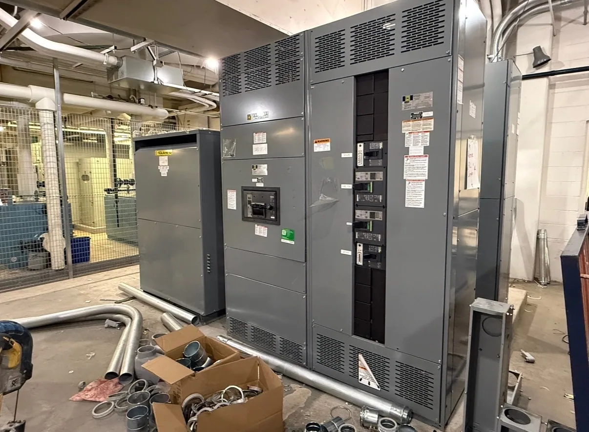
What a fused switch means
A fused switch is a switching arrangement that uses fuses to provide circuit protection as designed. The switch provides a means to open or close the circuit within its intended application; the fuse responds to specified overcurrent conditions by interrupting current. The two functions are related but not interchangeable: operating the switch is not the same action as a fuse clearing a fault.
The exact construction and function depend on the equipment and its design. The term may refer to a switch-fuse device or to a fused switching arrangement within a larger assembly. It does not, by itself, state voltage class, current rating, interrupting capability, fuse type, enclosure, or suitability for a particular duty. Those details must be confirmed from the equipment documentation and project requirements.
How switching and fuse protection differ
A fuse is selected to respond to current conditions according to its characteristics. A switch is selected for its intended switching and isolation duties. Whether a particular switch can interrupt load current, how it operates, and what safe isolation procedure applies are design-specific questions. Do not assume that a fused switch can interrupt every fault current or serve as a substitute for a separate protective device.
Fuse selection affects more than the nominal current value. The responsible engineer considers the circuit, available fault current, equipment capability, expected load, and coordination with upstream and downstream protection. Fuse time-current behavior and the equipment manufacturer's requirements matter. A fuse that appears to match a load value may not provide the intended protection or coordination in the actual system.
Place in a low-voltage switchgear project
In a low-voltage switchgear project, a fused switching device may be one element in a distribution arrangement, but it is not synonymous with the entire switchgear assembly. For example, an engineer might evaluate whether a feeder should use a fuse-based switching arrangement or a circuit breaker. The answer depends on the circuit's protective functions, operating needs, coordination objectives, and the equipment specification—not on terminology alone.
That choice can affect how the rest of the system is designed. The project team should establish what the device protects, how it relates to upstream and downstream devices, and whether separate sensing, metering, or control functions are required. A fused switch does not inherently provide electronic trip settings, protective relays, or the sensing inputs used by other schemes. Any such functions must be defined separately and verified against the selected equipment.
Conceptual example and common misunderstandings
Assume a project engineer is reviewing a low-voltage feeder and asks whether a fused switch is appropriate. No voltage, current, fault level, fuse class, or equipment rating is assumed here. The engineer would first identify the circuit and its load, then review system fault information, required protection, coordination, and the intended operating and isolation method. Only after that review can the engineer specify an appropriate device and compatible fuses.
A common misunderstanding is that “fused” guarantees protection for every connected condition. It does not: the fuse and assembly must be suitable for the application, and other protective functions may still be needed. Another is that a switch can always clear a fault because it can be opened manually. Switching capability and fault interruption are distinct design matters. The specification must state the intended duties and the responsible engineer must verify them.
Related protection terms
Protective relay selection is a related but different subject. A relay measures or evaluates inputs and issues a protective action through equipment designed to carry it out; a fuse is a direct-acting protective element with its own operating characteristics. A project may use either approach or combine protective functions, depending on its design. Confirm sensing inputs, control power, trip or operating interfaces, and coordination responsibilities where relays are involved.
A trip unit is also distinct from a fuse: it is associated with circuit-breaker protection and operation. Comparing a fused switch with a breaker and trip unit therefore requires comparing functions and application requirements, not just names. These terms describe different parts of a protection scheme, and none alone establishes that a complete system meets a project's needs.
Questions to resolve before specifying
Before requesting new equipment, provide the responsible supplier and engineer with the one-line diagram, system voltage class, circuit purpose, load information, available fault-current data, and project protection objectives. Identify required switching duties, operating method, space or enclosure constraints, and any monitoring or control interfaces. Ask which fuse type and characteristics are proposed, what equipment documentation supports their use, and how coordination will be evaluated.
Also clarify the boundary between the fused device and the broader assembly: what is included, which ratings and standards apply to the specific design, and what project information is still needed. For a new low-voltage switchgear assembly, confirm applicable listing and ratings against the actual configuration rather than assuming they follow from the term “fused switch.” The equipment supplier can review the defined specification and confirm configuration, availability, and delivery details for the order.
Used precisely, “fused switch” identifies a switching arrangement that works with fuses for circuit protection; it does not replace a complete equipment specification. Resolve the protection scheme, device duties, interfaces, and applicable design requirements with qualified project professionals before finalizing the equipment. This keeps the glossary term useful while ensuring the selected new distribution equipment matches the actual application.