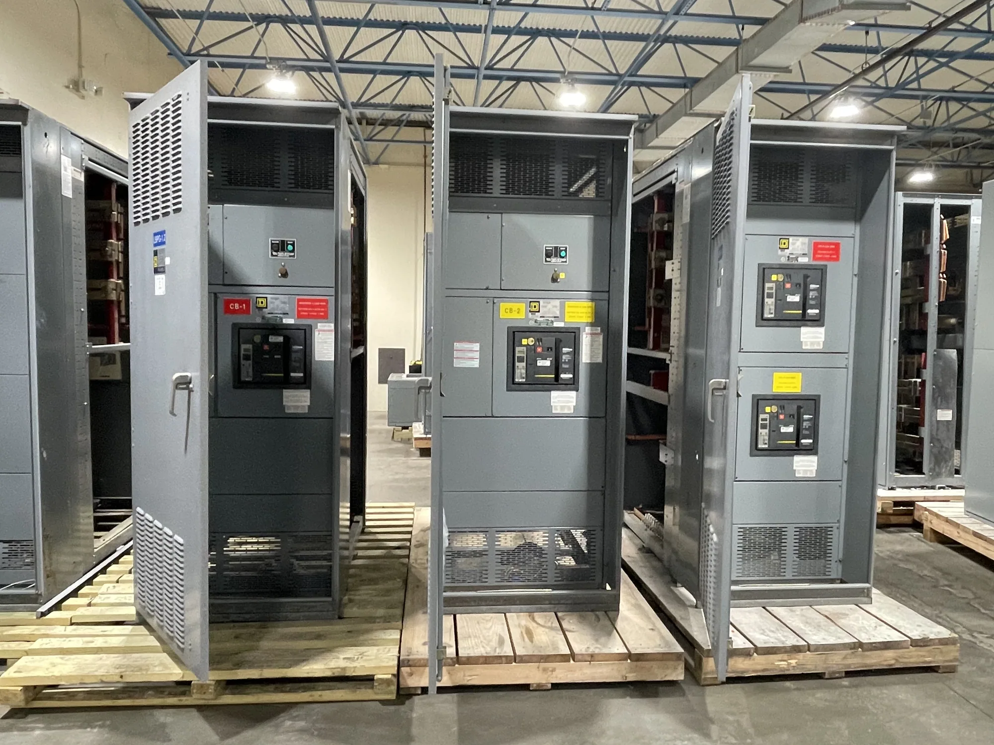
What a trip unit does
A trip unit is the device or functional assembly that causes a circuit breaker to open when it detects specified electrical conditions. In low-voltage distribution equipment, it commonly evaluates current measured by sensors and signals the breaker’s operating mechanism when a protection criterion is met. The breaker interrupts the circuit; the trip unit determines when a configured condition calls for that action.
The term can refer to an electromechanical, electronic, or other breaker-specific implementation, depending on the equipment design. Its exact functions and interfaces are not universal. A trip unit should therefore be understood in the context of the breaker and assembly it belongs to, rather than as a standalone protection device with identical capabilities across manufacturers and models.
Why the term matters in low-voltage equipment
For a new low-voltage switchgear project, the trip unit is one part of a protection system that includes the breaker, sensing components, conductors, connected loads, and upstream and downstream protective devices. The project engineer must determine how the selected breaker responds to relevant faults and overload conditions. The trip unit’s available functions and adjustable settings influence that response, but settings alone cannot establish a suitable design.
For example, a project may require distinct responses to sustained overcurrent and high-magnitude fault current. Whether a particular trip unit provides those functions, how they are named, and which settings are available must be confirmed for the proposed breaker. Equipment voltage class, available fault information, load characteristics, and the protection study all matter. Do not assume that a trip unit’s feature label or adjustment range proves coordination or suitability.
Sensing, control, and interfaces
Trip units depend on the sensing arrangement specified for the breaker. Ask how current is detected, what components are included, and whether the sensing arrangement supports the intended protection functions. Electronic units may also have control-power, display, communication, or accessory requirements; these are model- and configuration-dependent. Confirm which functions operate without auxiliary power and what happens if an external supply or communication connection is unavailable.
Where trip information or remote interfaces are needed, identify the project’s monitoring and control requirements early. A communication feature does not itself provide protective coordination, and a monitoring connection should not be confused with the trip function. The equipment supplier and responsible engineer should confirm compatible accessories, wiring interfaces, and any required documentation against the actual breaker and assembly specification.
Settings and coordination are project decisions
Trip-unit settings should follow the responsible engineer’s protection and coordination work, not a generic example or a field guess. Time-current curves help show how protective devices may respond over time at different current levels. Comparing the trip unit’s applicable curve with upstream and downstream devices can reveal whether the intended selectivity is achievable, subject to the equipment data and study assumptions.
Consider a conceptual low-voltage switchgear design serving several distribution branches. Assume the engineer wants a branch breaker to respond to a fault while preserving service on unaffected circuits where the design permits. The engineer would review the trip unit’s available functions and settings alongside breaker characteristics, conductor limits, fault-current information, and other protective-device curves. No particular setting or outcome follows from this example; those depend on verified project inputs.
Common misunderstandings and related terms
A trip unit is not the same as a protective relay, although both can participate in protection. A relay is a separate protective device in some arrangements; a trip unit is generally associated with a circuit breaker and its trip operation. The project design determines which device is appropriate and how it interfaces with the breaker. Likewise, a time-current curve is a representation of response, not a trip unit itself.
Also avoid treating “trip unit” as a guaranteed set of features. Trip indication, ground-fault functions, communications, adjustable parameters, and other capabilities vary by product and configuration. Confirm the terms used in the breaker documentation, since similarly named functions can have different scope. For more context, compare the equipment-specific definition with the project’s protective-relay selection and time-current coordination requirements.
Questions to resolve before specifying equipment
- Which breaker and low-voltage switchgear configuration are being considered, and what trip-unit options are compatible?
- What protection functions are required by the design, and which are available in the proposed unit?
- What sensing inputs, control power, accessories, indication, or communication interfaces does the project require?
- Which fault-current, load, conductor, and coordination-study inputs will establish settings?
- What documentation, verification, and acceptance steps will qualified project personnel require?
When requesting new equipment, provide the one-line diagram, applicable specifications, known system data, required interfaces, and the responsible engineer’s protection criteria. Ask the manufacturer to confirm the proposed breaker and trip-unit configuration against those documents. South Carolina Switchgear Builders manufactures new equipment to specification, is US-built with all-American components, and ships nationwide. Availability and lead times depend on the order and must be confirmed. Final configuration, ratings, listing applicability, and delivery details require project-specific review.