What a short-circuit study calculates
A short-circuit study is an engineering calculation that estimates the prospective current that could flow if a fault occurs at one or more locations in an electrical distribution system. The analysis models the power sources, transformers, conductors, and other relevant system elements to determine fault-current values at selected buses or equipment terminals.
These calculated values are not measurements of current during normal operation, nor do they predict the exact outcome of a future fault. They represent modeled conditions based on the system configuration and assumptions provided to the engineer. The study’s scope, calculation method, and applicable project requirements should be established by the responsible electrical engineer.
Why results matter when selecting equipment
Prospective fault current is one input when evaluating whether protective devices and assemblies are suitable for their intended locations. Engineers compare study results with applicable equipment ratings, including interrupting capacity for devices and short-circuit current ratings or withstand capabilities for assemblies, as appropriate to the equipment and design. These terms describe distinct characteristics; one rating should not be assumed to substitute for another.
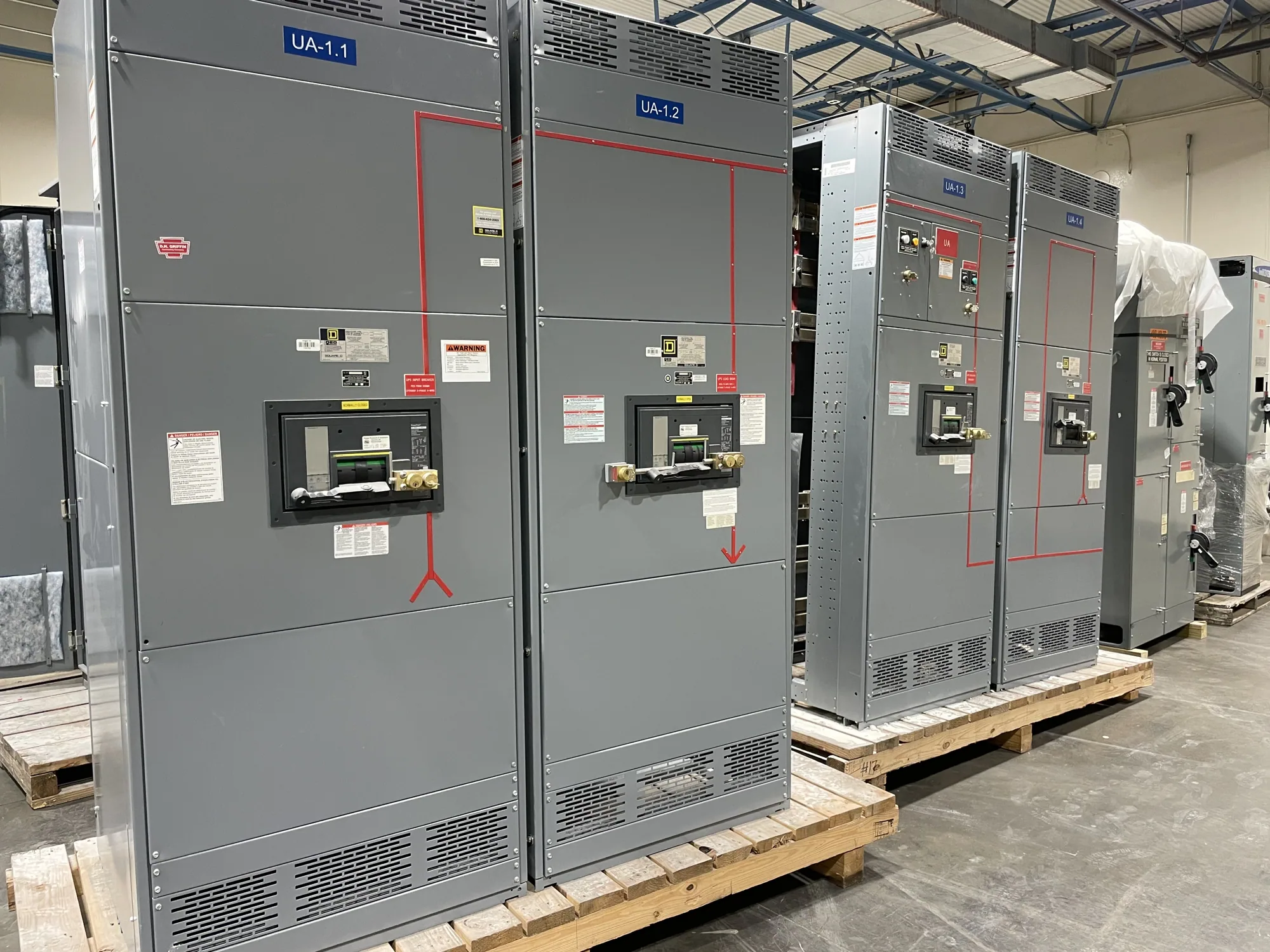
For a new low-voltage switchgear project, the engineer may use the study to assess available fault current at the proposed switchgear connection and review how the specified assembly and protective devices are intended to handle fault conditions. The equipment voltage class, configuration, protective-device selection, and project requirements all matter. A general product description cannot establish that a particular assembly is suitable; the actual design and ratings require review against the project study.
System details shape the calculation
Study results depend on the information used to represent the electrical system. Relevant inputs may include the utility source data available to the project, transformer characteristics, conductor sizes and lengths, generator or motor contributions where applicable, and the operating arrangement of ties or alternate sources. The engineer determines which inputs are needed and how uncertainty or alternate operating cases should be treated.
A project can have more than one meaningful configuration. For example, a normally open tie, a standby source, or a planned future addition may change the modeled paths and sources of fault current. The study scope should identify which configurations need analysis rather than assuming that one simplified operating condition represents every possible arrangement. Equipment selection should use results that correspond to the configuration and location being evaluated.
Conceptual example and common misunderstandings
Consider a hypothetical facility planning new low-voltage switchgear downstream of a transformer. The engineer models the source and distribution path, then calculates prospective fault current at the switchgear location. The example has no assumed numerical rating: the result must come from project-specific data. The engineer can then compare the calculated conditions with the proposed equipment’s documented ratings and identify any design questions requiring resolution.
A common mistake is to treat a transformer’s information, a protective-device rating, or a single system-wide figure as a complete answer for every equipment location. Fault current can vary across a distribution system, and operating arrangements can affect calculated values. Another mistake is to confuse a short-circuit study with a sequence-of-operations analysis: the former calculates fault-current conditions, while the latter concerns how protective devices are intended to operate in relation to one another.
Ratings, standards, and design review
Short-circuit study findings should be considered alongside the equipment specification and the applicable requirements for the specific assembly. For eligible low-voltage switchboards, UL 891 may be relevant, but applicability and any assembly listing must be confirmed for the actual design. UL 891 should not be treated as a blanket statement about all switchgear, and it does not apply to medium-voltage switchgear by virtue of this glossary definition.
Ask the responsible engineer to identify the study assumptions, locations analyzed, operating cases, and the equipment characteristics being checked. Ask the supplier to confirm the proposed equipment configuration and documented ratings against the project specification. Ratings, listing, testing, and standards applicability are design-specific matters; they should be verified for the equipment being supplied, not inferred from a product category or a general explanation.
Information to share for a new equipment project
When requesting a new switchgear quotation, provide the current one-line diagram, project voltage class, available source and transformer information, and the latest study results if available. Include the intended operating configuration, required protective devices, specified assembly ratings, and any project requirements identified by the engineer. Clearly mark unresolved items rather than filling gaps with assumptions; incomplete or changing source data can affect equipment review.
Coordinate the study and equipment review early enough to address discrepancies before the design is finalized. Confirm who will provide source data, who will interpret study results, and how revisions to the one-line diagram or operating arrangement will be communicated. South Carolina Switchgear Builders manufactures new equipment to specification, with availability and actual lead times confirmed for each order. Qualified personnel should handle installation, testing, and maintenance under applicable safety procedures.