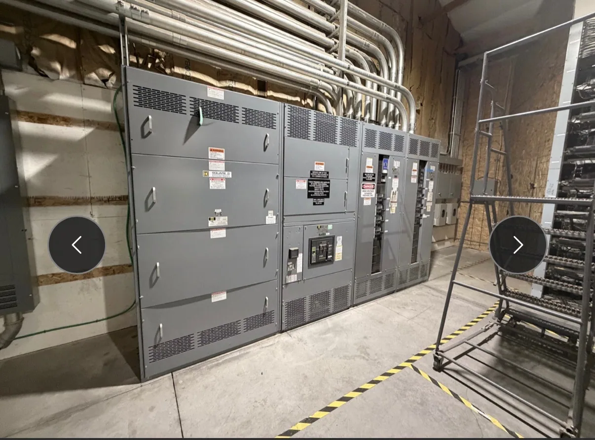
What a variable-frequency drive means
A variable-frequency drive (VFD) is an electronic motor-control device that varies the frequency of the electrical output supplied to an AC motor. Its output voltage is also adjusted as designed so the motor can operate at different speeds or meet a control objective. The precise control method and operating range depend on the drive, motor, and application; the term alone does not specify a complete system.
A VFD is not the same thing as switchgear. The drive controls a motor, while switchgear performs functions such as switching, protection, and isolation within an electrical distribution system. A project may include both, but the equipment arrangement and division of functions must be established by the responsible design team. A VFD does not, by itself, identify the required upstream protective devices or their ratings.
Why the drive matters to distribution design
Because a VFD uses power electronics, its electrical input and output should be considered as part of the full motor system. The project engineer should confirm the motor characteristics, operating profile, drive requirements, and the electrical source available at the installation. These details inform how the drive connects to distribution equipment and what protection, isolation, and coordination are appropriate for the specific design.
Do not assume that a drive changes the voltage class of the distribution equipment or that every motor-control arrangement has the same configuration. A medium-voltage switchgear project, for example, may involve a motor supplied through a drive, but the actual interface depends on the system design and selected equipment. Confirm the voltage class, connection arrangement, and scope of supplied components from the project specification rather than inferring them from the word “drive.”
Site conditions and equipment placement
Location can shape equipment choices and installation planning. Document expected ambient temperature, humidity, altitude, salt exposure, water exposure, dust or other contaminants, and whether the equipment is indoors or outdoors. These conditions may affect enclosure selection, ventilation, material choices, and equipment requirements, but suitability must be verified against the actual design and manufacturer documentation. A general environmental description is not a substitute for the site conditions the project engineer needs.
Also consider the space required for the drive, associated distribution equipment, cable routing, and safe maintenance access. Room layout, access paths, heat management, and the planned means of isolation should be reviewed together. The project team should identify who supplies the drive, who supplies upstream equipment, and who is responsible for connections and coordination. Those boundaries help prevent missing components or assumptions about work by another party.
Conceptual example and common misunderstandings
Consider a project that needs to vary the speed of an AC motor serving a process load. Assuming the responsible engineer selects a compatible motor and drive, the VFD adjusts the electrical output frequency and voltage as designed to control motor operation. The engineer then evaluates the source, protective arrangement, equipment interfaces, and site environment. This example illustrates the roles involved; it does not establish a particular rating, wiring scheme, or equipment selection.
A frequent misunderstanding is that a VFD is simply a switch or a substitute for all motor protection. Another is that specifying a drive alone settles upstream switchgear requirements. Neither conclusion follows from the term. Drive, motor, protection, and distribution equipment must be assessed as a coordinated system. Likewise, “medium-voltage switchgear” describes a distribution equipment category, not a drive type; determine whether the drive is within the switchgear supplier’s scope or furnished separately.
Information to gather before specifying
For an equipment discussion, provide the project voltage class and available system information, motor nameplate data, intended load and operating profile, and the drive manufacturer or model if already selected. Identify required operating modes, control interfaces, fault and protection requirements, and any known constraints on the electrical source. The responsible engineer should confirm which details are required and resolve conflicts between motor, drive, and distribution documents.
Include a site-conditions record with indoor or outdoor location, temperature and humidity expectations, altitude, salt or chemical exposure, water risk, available floor space, and access limitations. State who is furnishing and installing each major component, and identify requested documentation, testing, ratings, or listing requirements for review. These are project-specific matters: applicability and availability must be confirmed for the actual equipment and specification, not presumed from a general product description.
Coordinate the drive with new distribution equipment
When planning new switchgear or switchboards, share the drive and motor information early enough for the equipment supplier and project engineer to review interfaces and scope. South Carolina Switchgear Builders manufactures new equipment custom to specification, with US-built equipment and all-American components; availability and actual lead times depend on the order and must be confirmed. Nationwide shipping is available, while delivery dates and project-specific configurations require confirmation.
Before approving documents, ask the responsible engineer to verify the system arrangement, protective-device requirements, physical clearances, site conditions, and responsibility for installation and commissioning. Confirm applicable ratings, standards, testing, and any listing against the specific assembly and project documents. Installation, testing, and maintenance should be performed by qualified personnel under applicable safety procedures. Clear answers to these questions make the VFD’s role understandable and help the distribution equipment fit the project as designed.