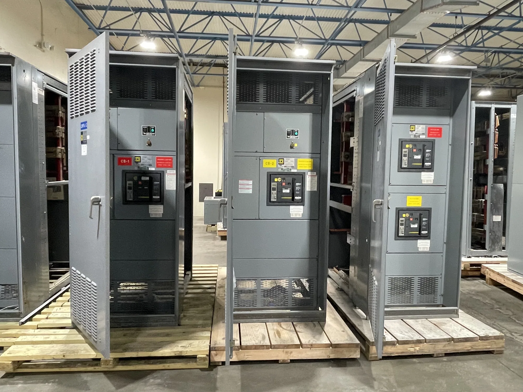
Define the distribution project around the process
Paper mill power projects can involve interconnected preparation, forming, pressing, drying, finishing and material-handling operations. The switchgear scope may serve a plant section, support a capacity change, replace an electrical lineup, or coordinate with a broader distribution upgrade. Begin by identifying which buses, feeders and loads are included, what equipment remains in service, and where the new assembly connects to the existing system.
Process continuity is a design input, not a promise that every load must remain energized during every fault or maintenance event. Ask operations and electrical engineering to identify loads that cannot tolerate interruption, loads that can be sequenced after a trip, and equipment that may be stopped within a planned outage. These priorities help define feeder groupings, operating arrangements and the information needed for protection and switching decisions.
Build the load picture, especially for motors
Large process motors can influence feeder selection, starting arrangements and system studies. Provide a current motor list with nameplate data, operating duty, starting method, expected starts, and the driven process where known. Include pumps, fans, refiners, conveyors and other significant loads rather than treating the paper machine as one undifferentiated demand. The responsible engineer should confirm which loads are served by the proposed lineup and which belong to motor-control equipment elsewhere.
Motor starting can affect voltage conditions and coordination with upstream and downstream protective devices. Whether a motor starts across the line or uses another arrangement depends on the actual motor, process requirements and electrical system. Share available short-circuit and coordination information, existing protective-device data, and any study requirements with the equipment manufacturer. Do not assume a switchgear feeder alone resolves starting performance or process-control needs.
Specify exposure from measured site conditions
Paper production areas may present moisture, condensation, heat, dust, fibers, washdown or corrosive contaminants, but exposure varies substantially by room and process location. Document the conditions at the proposed installation point instead of selecting an enclosure from the industry name alone. Identify indoor or outdoor placement, ambient conditions, ventilation, nearby steam or water sources, cleaning practices, and the possibility of condensation during shutdown or seasonal changes.
Enclosure construction, barriers, ventilation and equipment placement should be evaluated against the actual environment and applicable project requirements. A more protective enclosure may affect dimensions, cooling, access and installation details, so it is not automatically the best choice in every location. Have the project engineer confirm environmental criteria and required ratings for the specified assembly. Record constraints such as narrow access routes, floor loading, cable entry direction and clearance around doors.
Coordinate protection and operating boundaries
Protection settings and device selection depend on the system study, equipment ratings and coordination objectives. Provide the available one-line diagram, source information, transformer data, grounding approach and known fault-current or study results when available. The engineer of record should establish the required ratings and protection scheme for the actual installation. Manufacturer review can then address whether the proposed equipment configuration aligns with that documented basis.
Also define interfaces with transformers, generators, utility service, process controls and other distribution equipment, where applicable. Clarify which party supplies each connection, metering or control component, and who is responsible for field verification and commissioning. Switchgear, switchboards and motor-control centers serve different functions; the right scope may use more than one equipment type. Identify the boundary rather than assuming every motor feeder belongs in one lineup.
Balance maintainability with shutdown constraints
Planned outages shape the sequence for removal, setting, cable termination, inspection and return to service. Share the target outage window as a project constraint, not as a guaranteed delivery or installation date. Equipment availability and actual lead times depend on the order and must be confirmed. Allow the project team to assess design review, drawing approval, manufacturing, shipping, site readiness and work by qualified installation personnel as separate schedule activities.
Consider how operators will isolate sections, access devices and restore loads after authorized work. A lineup arrangement that supports a preferred operating sequence may require more space or different compartment divisions; those tradeoffs need engineering review. Do not plan energized installation or maintenance. Switching, testing and maintenance must be performed by qualified personnel following applicable safety procedures and the site's approved practices.
Prepare a useful quotation and engineering package
For a focused quotation, assemble the latest one-line, load and motor schedules, equipment scope, system data, environmental survey, physical layout and cable-entry requirements. Include process priorities, known interfaces, project standards and the planned outage window. Mark uncertain values clearly instead of presenting estimates as confirmed ratings. A complete request lets the manufacturer identify questions early and develop a configuration to the supplied specification.
South Carolina Switchgear Builders manufactures new, US-built equipment using all-American components, with custom configurations and nationwide shipping. Availability and lead times require confirmation against the order. Before release, the project team should review drawings, ratings, applicable listing requirements, interfaces and delivery assumptions for the particular assembly. Confirm which requirements apply to the design rather than presuming a standard or certification covers every configuration.
Make the next step a coordinated scope review
Start with the motor inventory, one-line diagram, environmental observations, process priorities and outage constraints, then identify missing engineering data and responsible reviewers. This establishes a practical basis for comparing equipment arrangements without overstating what the switchgear can accomplish on its own. When scope, interfaces and assumptions are documented, the buyer and project team can evaluate a new lineup against the mill's real operating needs and move toward a specification-backed quotation.