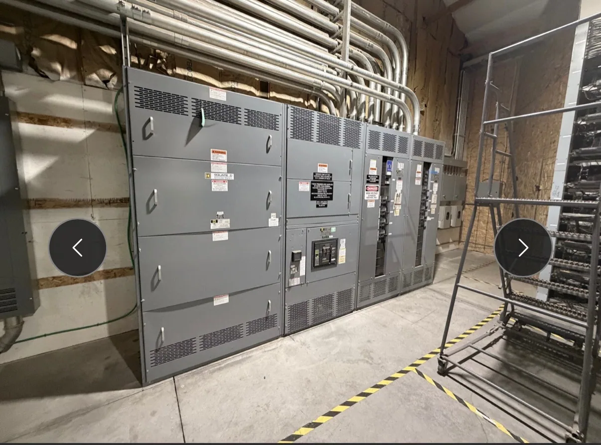
Start with the production and distribution context
Automotive manufacturing facilities bring together production lines, motor loads, utility and plant distribution, and support systems whose operating needs may differ by area. Instrumentation and communications planning should begin with those operating needs, not with a default list of devices. Identify which electrical information operators, maintenance teams, facility engineers, and control-system owners need to make decisions, and where they need to receive it.
Consider planned expansion and the way work is sequenced. A future line, added process equipment, or changed production schedule may affect feeder assignments, metering priorities, and how an outage can be staged. These possibilities do not establish particular ratings or configurations; the project engineer must determine those from the load study, distribution design, and applicable project requirements.
Define a useful metering and status point list
Build a point list around specific decisions. For each proposed measurement or status point, state what it represents, who uses it, where it originates, and whether it is needed continuously, for alarms, or for troubleshooting. Possible subjects for project review include electrical measurements at selected distribution sections, breaker or switch position, and equipment alarm indications. Confirm which points are available from the selected design.
A disciplined list helps avoid both omissions and unnecessary complexity. A broad request for “full visibility” is difficult to price, engineer, and test unless it identifies signals, units, scaling, update expectations, and intended use. The owner, electrical engineer, controls integrator, and equipment supplier should resolve ambiguous terms before drawings are finalized. Record exclusions as carefully as included points so each party understands the intended boundary.
Coordinate communications and integration boundaries
Specify the communications interface in terms the responsible controls and electrical teams can review: required protocol, physical connection, network ownership, data mapping, and the party responsible for configuration and integration. Do not assume that equipment will connect to a facility network merely because a protocol is named. Confirm the selected equipment’s available interface and the customer’s requirements against the actual specification.
Set cybersecurity boundaries with the owner’s information-technology and operational-technology stakeholders. Clarify whether the equipment interface is isolated, connected through a customer-managed network, or handled another way defined by the project. Identify who supplies network hardware, assigns addresses, approves access, and maintains any gateway or configuration. The equipment supplier should not be presumed responsible for plant-wide cybersecurity or controls programming unless the agreed scope expressly includes it.
Plan feeder segregation and staged outages
Feeder organization can influence how production areas are monitored and how maintenance or construction is coordinated. Work with the electrical engineer to identify which loads and areas belong to each feeder, which information helps operators understand distribution status, and whether the intended arrangement supports the facility’s outage plan. Any segregation strategy depends on the one-line diagram, load requirements, protective-device coordination, and the owner’s operating procedures.
For staged outages, define the sequence and interface responsibilities early. The project team should identify equipment boundaries, required isolation points, dependencies on controls or communications, and the approvals needed before each stage. Switchgear instrumentation can provide selected status or measurement information, but it does not itself establish a safe work condition. Installation, testing, and maintenance must be performed by qualified personnel under applicable safety procedures.
Consider the service-entrance interface carefully
Service-entrance switchgear is one possible point for metering or status requirements, not a universal answer for every automotive facility. First determine the project’s distribution arrangement and the information needed at that boundary. Ask whether the requested points belong at the service entrance, at downstream equipment, or in more than one location, and verify that each proposed point is supported by the specified assembly.
When requesting a manufacturer proposal, provide the one-line diagram, equipment scope, electrical ratings, relevant drawings, point list, protocol and interface expectations, and any required project standards. State which documents are preliminary and identify open decisions. If the project includes low-voltage switchboards, ask whether UL 891 applies to the specific design and verify any assembly listing directly; that standard should not be applied indiscriminately to all switchgear.
Use a project checklist before equipment review
- Describe production areas, major load groups, planned expansion, and the distribution sections included in the purchase.
- Provide the current one-line diagram, available fault and load information, equipment ratings, and the engineer’s applicable standards and design assumptions.
- Submit a point list identifying each measurement or status indication, its intended use, and the equipment location requested.
- Name the protocol, connection, data-mapping expectations, network owner, cybersecurity reviewers, and responsibility for integration and testing.
- Document outage stages, feeder boundaries, interfaces with controls, acceptance responsibilities, and items that remain undecided.
South Carolina Switchgear Builders manufactures new switchgear and switchboards to specification, with US-built equipment and all-American components, and ships nationwide. Availability and actual lead times depend on the order and must be confirmed. A complete, coordinated specification gives the manufacturer and project team a practical basis to review the proposed equipment, clarify interfaces, and align procurement documents with the facility’s production and maintenance plans.