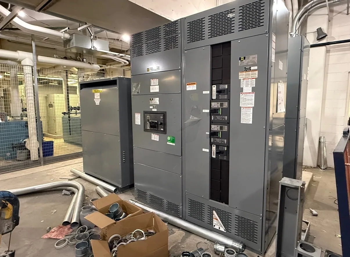
Start with the production and project scope
Manufacturing facilities often combine process equipment, building services and support systems on a shared electrical distribution plan. A switchgear project may serve a new production line, replace equipment during a planned shutdown, or support a staged capacity expansion. Define which of these situations applies before comparing equipment. The intended scope shapes the required interfaces, outage plan and information the manufacturer needs to develop a suitable configuration.
Map the electrical path from the incoming source through the proposed assembly to the downstream distribution. Identify the loads that must remain in service, the production areas affected by an outage and any temporary operating arrangement proposed by the project team. Do not assume that one replacement lineup can be connected without changes to existing conductors, foundations or downstream protection. The responsible engineer should verify these interfaces against current drawings and site conditions.
Describe loads, motors and operating patterns
Prepare a load schedule that separates major process loads from lighting, HVAC, controls and other facility services. For production equipment, provide nameplate information and the project engineer’s expected operating profile, including simultaneous operation, duty cycles and planned additions. Motor starting methods and starting frequency can influence feeder and upstream equipment decisions. The manufacturer needs the specified system conditions; it should not infer them from a general description such as “motor-heavy plant.”
Consider how the plant behaves during startup, routine production, shift changes and recovery after an interruption. Ask the responsible engineer to assess whether starting events, load changes or operating sequences affect the proposed distribution design. If a production line is being added in phases, distinguish loads included in the initial purchase from future provisions. Clear boundaries help avoid both an unnecessarily broad initial scope and a configuration that leaves no practical path for the planned expansion.
Coordinate protection, ratings and measurement
Provide the available fault-current information at the equipment connection point, the source characteristics and the existing protective-device data. Select interrupting and withstand capabilities, continuous-current ratings and protection functions for the specific system and approved study assumptions. These are not interchangeable checklist values: the project engineer must verify the required ratings and coordination for the actual installation. Any proposed settings or selective-coordination objectives should be reviewed against the full upstream and downstream device arrangement.
Specify metering and monitoring needs by function rather than by a broad request for “plant data.” Identify which incomers, production feeders or loads need measurement, what values operators need to observe, and whether signals must interface with an existing control or monitoring system. Confirm communication protocols, auxiliary power, instrument-transformer requirements and wiring responsibilities with the project team. These details affect compartments, wiring and terminal interfaces, so they are best resolved before the equipment design is finalized.
Balance maintainability with production continuity
In a plant where a shutdown has a narrow approved window, access and maintainability deserve early attention. Define aisle and room constraints, cable entry directions, working clearances and the route for moving equipment into position. Provide applicable building and site drawings rather than relying on an assumed standard room layout. Qualified personnel must plan installation, inspection, testing and maintenance under the applicable safety procedures; no equipment arrangement removes the need for those procedures.
Discuss the operating consequences of isolating a feeder or section, and whether the project includes an approved alternate supply or staged cutover. Do not assume that adding a tie, transfer arrangement or spare section is automatically appropriate. Each option introduces design, protection and operating considerations that must be evaluated for the actual plant. A realistic outage schedule should account for the full scope of field work and required approvals, without treating equipment delivery as the only schedule constraint.
Plan for expansion without overbuilding
Growth forecasts are useful when they identify specific expected loads, timing and uncertainty. Ask the engineer to distinguish committed additions from possible future lines, and to state what capacity or physical provisions are actually required now. Spare spaces, future feeder provisions and larger bus capacity may affect footprint, cost and coordination. Avoid specifying vague “room for growth” without defining the intended provision and confirming that it fits the electrical and physical design.
For a hypothetical staged project, a facility might install distribution for one production area while reserving a defined interface for a later phase. The right approach depends on the source, load plan, available space and approved operating strategy. Manufacturer drawings and project reviews should verify dimensions, connection points and division of responsibilities before release. Changes made after design approval can affect schedule and equipment configuration, so route revisions through the project’s formal review process.
Prepare a complete manufacturing RFQ
For a useful quotation, assemble one current package: one-line diagram, load and feeder schedules, source and fault-current data, required voltage and ratings, protection expectations, metering scope, physical constraints and desired delivery window. Include existing equipment interface details and clearly mark information that remains pending. State whether the request covers switchgear, associated switchboards, motor-control equipment or defined portions of the distribution system; those products serve different functions and should not be treated as interchangeable.
South Carolina Switchgear Builders manufactures new equipment, including custom configurations to specification, and ships nationwide. Availability and actual lead times depend on the order and must be confirmed. Before purchase, have the responsible engineer and project team review the proposed equipment against the application, drawings, ratings, applicable standards and site interfaces. Confirm any listing, testing, delivery and installation requirements for the specific assembly, then align submittal approval and outage authorization with the facility’s production plan.