Relay selection starts with the equipment design
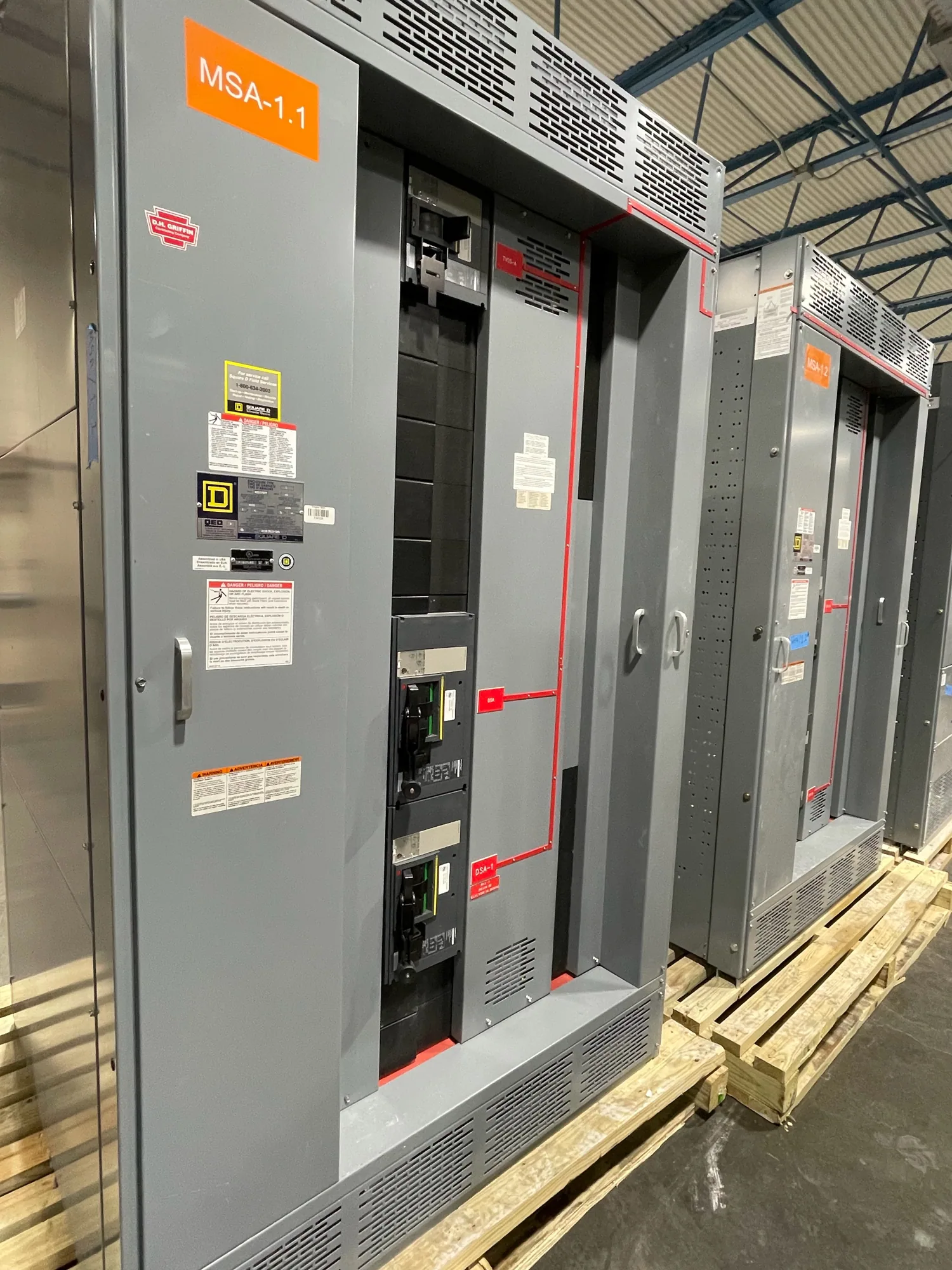
Protective relay selection for arc-resistant switchgear is not a standalone device choice. The relay, current and voltage sensing, interrupting devices, control circuits, enclosure, and installation configuration work together. An arc-resistant rating applies only to an applicable tested design used within its documented limits; adding a particular relay or changing its settings does not independently create or preserve that rating.
Begin with the project’s equipment specification and the manufacturer’s documentation for the proposed assembly. Confirm the stated accessibility type, configuration, applicable rating information, and any conditions or exclusions. The responsible engineer should determine whether the intended arrangement and installation match the documented design. Relay decisions should support that arrangement rather than introduce unreviewed changes to sensing, control, or protective-device interfaces.
Define protection objectives and system inputs
List the functions required at each section or feeder, such as overcurrent protection, ground-fault protection where applicable, or other functions identified by the protection study. The engineer should establish which devices detect each condition, which circuit breaker or other device is expected to interrupt it, and how alarms or trip signals are communicated. Do not assume every relay function is needed, available, or appropriate for every application.
Provide the system information needed to evaluate those objectives: one-line diagrams, source and transformer data, grounding method, load characteristics, available fault-current information, and upstream and downstream protective-device data. Identify motors, generation, tie breakers, and operating modes that could affect fault current or coordination. Any unknown values should be clearly marked for confirmation; relay pickup values and time delays should come from project-specific engineering, not a generic example.
Match relays to sensing and control interfaces
Relay capability must match the specified current and voltage inputs, sensor or transformer arrangement, wiring method, and device documentation. Confirm the number and type of inputs, required measurement functions, trip outputs, communication needs, and available control power. The equipment design must provide compatible interfaces, and the engineer should verify that the selected sensing approach is suitable for the protective functions and the assembly configuration.
Control power deserves explicit review. Identify the required source, voltage, supervision or monitoring needs, and behavior during loss of normal power. Confirm how relay outputs connect to the intended trip circuit and how status, alarms, and interlocks are handled. A relay’s feature list alone does not establish that the complete protection path will operate as intended; device documentation, wiring diagrams, and the project’s control scheme must agree.
Coordinate settings with the tested arrangement
Settings should be developed by a qualified protection engineer using the system study and the documentation for the selected relay and interrupting device. Review coordination across relevant operating modes, including source changes or tie operation where present. Examine whether the selected functions and settings satisfy the project’s protection objectives while limiting unnecessary interruptions. No single pickup, curve, or delay can be prescribed without the actual system data and engineering review.
Also examine whether proposed sensing, trip logic, or control changes affect the equipment configuration covered by its arc-resistant documentation. Accessibility, installation details, and tested design limits are assembly-specific considerations. Ask the manufacturer and responsible engineer to identify any required configuration boundaries and to review deviations before release. Relay coordination and arc-resistant design are related review areas, but one should not be represented as proof of the other.
Consider an illustrative manufacturing application
For an automotive manufacturing facility, an engineer might evaluate a main section, production feeders, motor loads, and a bus tie. This is an illustrative arrangement, not a statement about a particular plant or equipment rating. The engineer would determine which operating modes matter, what fault and load data are available, and where selective coordination is required by the project’s design criteria.
Unknown inputs—such as source contribution, motor starting conditions, grounding details, or tie status—must remain open engineering questions until verified. The team should review the protection study, relay documentation, proposed sensing, trip paths, and the exact arc-resistant equipment configuration together. Standards applicability and any required calculations should be evaluated by qualified professionals against the actual project scope; no assumed value or generic relay setting substitutes for that review.
Prepare a useful specification and submittal review
For a quotation and design review, provide the one-line diagram, system voltage and available fault information, grounding arrangement, protection study or design criteria, and the required feeder and breaker schedule. Include preferred relay functions or approved device requirements, sensing details, control-power expectations, communication interfaces, and operating modes. State which information is preliminary and who will resolve each open item before final settings and equipment approval.
Request equipment-specific documentation showing the proposed relay interfaces, sensing and control arrangements, protection-device coordination responsibilities, and applicable arc-resistant design information and exclusions. Confirm which settings or calculations are project-engineered and what review is expected before shipment or installation. Availability, configuration, and delivery timing depend on the confirmed specification. New equipment can be custom to specification, with US-built options and nationwide shipping; actual lead times must be confirmed for the order.
Close design gaps before equipment release
Before approval, have the responsible engineer and project team reconcile the relay schedule, diagrams, study assumptions, and manufacturer’s equipment documentation. Resolve mismatches in sensing, control power, trip logic, communications, and operating modes, and document any approved deviations. Installation, testing, and maintenance should be performed by qualified personnel following applicable safety procedures and the equipment documentation.
A clear, coordinated specification helps the manufacturer evaluate the intended assembly and helps the engineering team complete protection decisions on project facts. Treat the relay as one part of a documented system: its functions and settings must suit the electrical design, while the arc-resistant claim remains tied to the applicable tested equipment configuration and its stated limits.