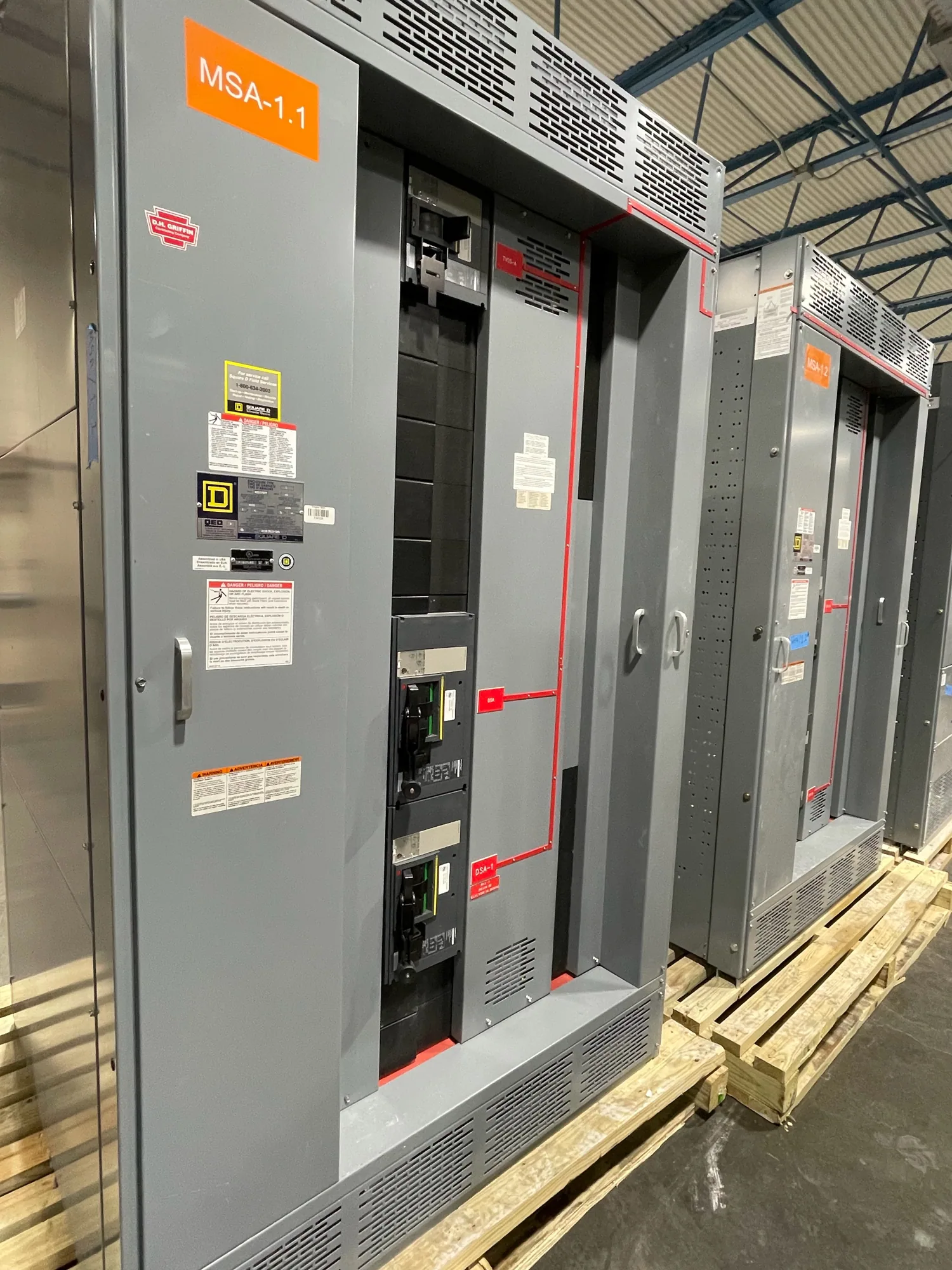
Where coordination enters a generator system
In a generator paralleling system, selective coordination concerns how protective devices respond to faults at different points in the distribution system. The goal is to limit an interruption to the portion of the system affected, where the project requirements and device behavior support that outcome. It is not established by the switchgear nameplate or a general statement that equipment is coordinated; it requires review of the actual protective-device combinations and operating conditions.
Generator paralleling switchgear brings sources together through equipment designed around the specified system arrangement. Its source breakers, bus protection, feeder devices, controls, and connections to downstream distribution all affect how a fault is detected and cleared. Coordination review therefore spans the generator equipment and the distribution it supplies. The exact equipment boundary matters: identify which devices are part of the supplied assembly and which are elsewhere in the customer’s system.
Evaluate the specified operating modes
Protective behavior may differ according to whether one generator or several are operating, which sources are connected, and how the system is configured for normal, standby, or other specified conditions. Parallel operation can change the available fault contribution compared with a single-source condition. The responsible engineer should identify the credible configurations to evaluate rather than assume that one set of time-current curves represents every operating mode.
Coordination also has to work alongside synchronization, source selection, load priority, and control logic. A protective trip may affect which generators remain connected, which loads are served, and whether the system can continue operating as intended. Those relationships do not mean that controls replace overcurrent protection. Instead, the design review should clarify the roles and interfaces of protective relays, breaker trip functions, generator controls, and any load-shedding or transfer scheme specified for the project.
Balance continuity with fault protection
Selective coordination is a design objective within a stated range and set of conditions, not a promise that every upstream and downstream device will coordinate for every possible fault. Engineers compare device time-current behavior and relevant equipment limits against the project’s required fault-current range. A setting or device choice that helps preserve service for one condition can affect clearing time or protection at another point, so both continuity and equipment protection need explicit review.
Upstream and downstream devices may have adjustable or fixed characteristics, and their coordination depends on the actual models, trip units, relay functions, settings, and tolerances. Provide manufacturer data where available and distinguish proposed values from confirmed settings. The reviewing engineer should assess the complete protective-device chain, including utility or generator source information and downstream equipment data, then identify any limitations, exceptions, or assumptions rather than presenting a curve comparison as a blanket guarantee.
Consider a manufacturing application carefully
For an illustrative automotive manufacturing facility, imagine a project with several generators, a paralleling lineup, and feeders serving production and support loads. This example supplies no generator sizes, fault-current values, device models, load priorities, or required coordination range; those values are unknown and must not be inferred. The project team would define which loads require continuity and which operating configurations must be analyzed before selecting protective devices or settings.
That review could reveal tradeoffs between maintaining selected production loads and clearing a fault within equipment limits. The facility label alone does not establish a particular electrical code requirement or coordination outcome. A qualified project engineer should confirm applicable codes, standards, owner criteria, available fault current, device performance, and the study method for the actual installation. The switchgear supplier can use approved design inputs to develop equipment to specification, but system-level engineering assumptions must be clearly assigned and documented.
Define the project data and deliverables
A useful specification identifies system voltage and frequency, generator and utility source arrangements, operating sequences, bus configuration, grounding approach, and the locations of incoming and outgoing connections. Include one-line diagrams, load information, available fault-current data, and the required coordination range and operating cases. Identify known protective-device manufacturers and models, proposed trip units or relays, and who is responsible for providing and approving final settings.
Also state the intended equipment scope and interfaces: generator breakers, tie breakers, feeder breakers, protective relays, synchronization functions, metering, controls, communications, and terminal points. Ask which components are included, which are by others, and what documents are needed to coordinate them. Equipment-specific submittals may include drawings, device data, control descriptions, and setting information as applicable to the confirmed design. Confirm deliverables and review responsibilities before release for manufacture.
Coordinate review before equipment release
Before approving a design, resolve discrepancies between the one-line diagram, equipment schedule, protective-device list, and study assumptions. Confirm whether the coordination analysis covers each stated source configuration and the downstream devices within the project boundary. Ask how revisions to generator data, feeder lengths, breaker models, or operating sequences will be handled, since such changes can affect the analysis and require renewed review.
South Carolina Switchgear Builders manufactures new generator paralleling switchgear to specification, with US-built equipment and nationwide shipping; availability and actual lead times depend on the order and must be confirmed. Provide the project’s approved requirements and identify open engineering questions when requesting a quotation. Final ratings, device selections, listing applicability, delivery dates, and coordination conclusions must be verified for the specific design and supplied equipment. Installation, testing, and maintenance are the responsibility of qualified personnel following applicable safety procedures.